English
  日本語
日本語  한국어
한국어  français
  Deutsch
  русский
  português
  العربية







What are you looking for?

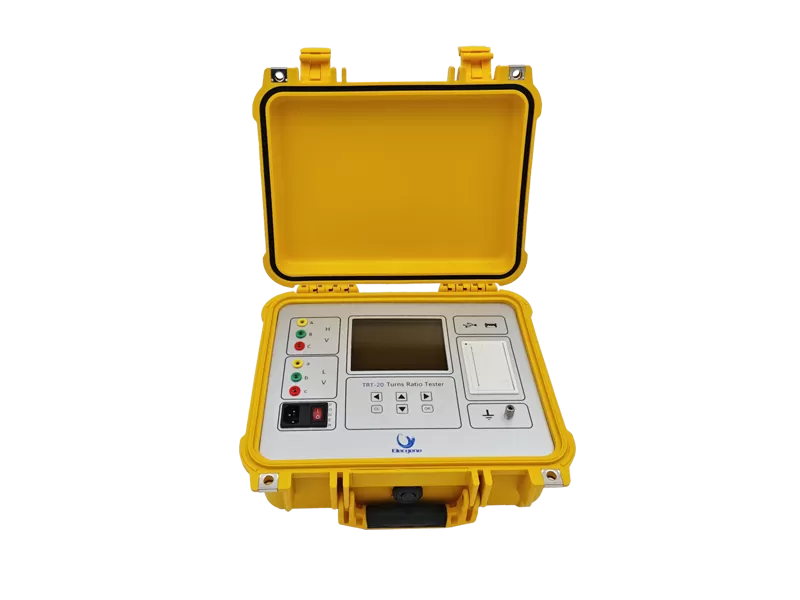
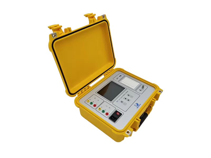
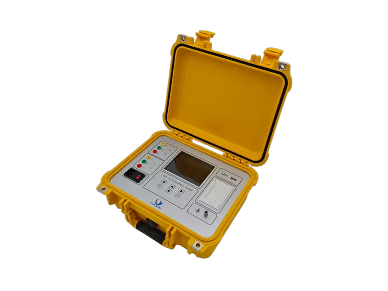

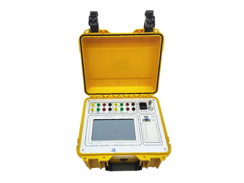
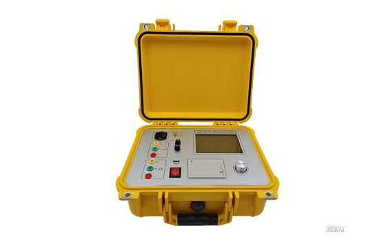
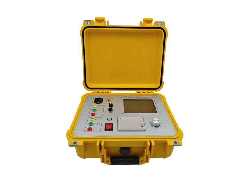
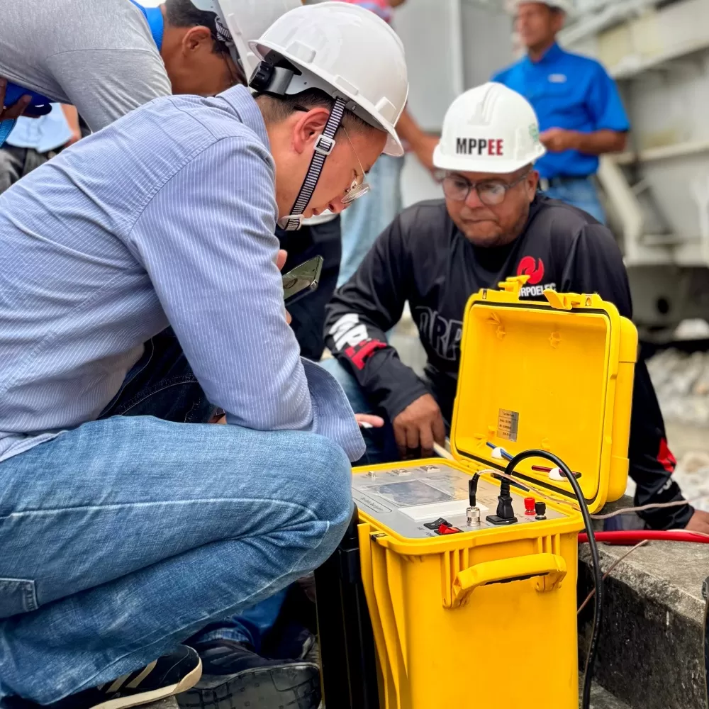
The TRT-20 TTR tester is designed to test all power, instrument (CTs and PTs), and distribution transformers without the need of traditional high voltage excitation. The electrical integrity tester is also an innovative product with compact size, more portable and easy to carry. With three phase output voltage, testing is up to five times faster than previous phase-by-phase switching single instruments, easier to test phase shift measurement, vector recognition, winding balance.
Built in printer
Battery powered(Optional)
Displays % error vs. name plate value
3-phase test voltage - fast testing of all transformers
The TRT-20 is widely used for:
Turns ratio test
Phase shift measurement
Vector recognition
Winding balance
Power transformer commissioning
Distribution transformer maintenance
Substation preventive maintenance
Current transformer (CT) ratio testing
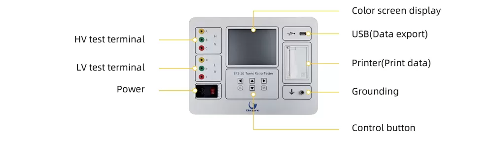
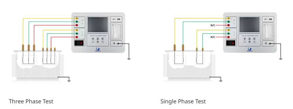
| Range | 0.9~10000 |
| Accuracy | ±(Reading×0.1%+2 words)(≤500) |
| ±(Reading×0.2%+2 words)(>500≤3000) | |
| ±(Reading×0.3%+2 words)(>3000) | |
| Resolution ration | 0.9~9.9999(0.0001) |
| 10~99.999(0.001) | |
| 100~999.99(0.01) | |
| 1000~9999.9(0.1) | |
| 10000 and above(1) | |
| Power supply | 200~240VAC,50/60 Hz |
| Temperature | -10℃~50℃ |
| Relative humidity | ≤90%,No dew |
| Net size | 325×225×125 mm |
| Net weight | 3.8 kg |
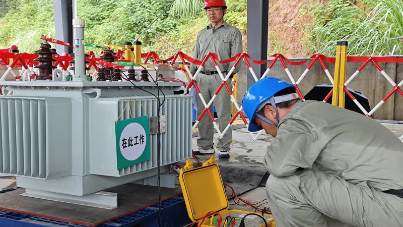
Transformer turns ratio testing verifies that the transformer winding ratio matches its nameplate specifications. It helps identify winding defects, shorted turns, tap changer problems, and incorrect connections before the transformer is placed into service. Regular TTR testing improves transformer reliability and reduces the risk of unexpected failures
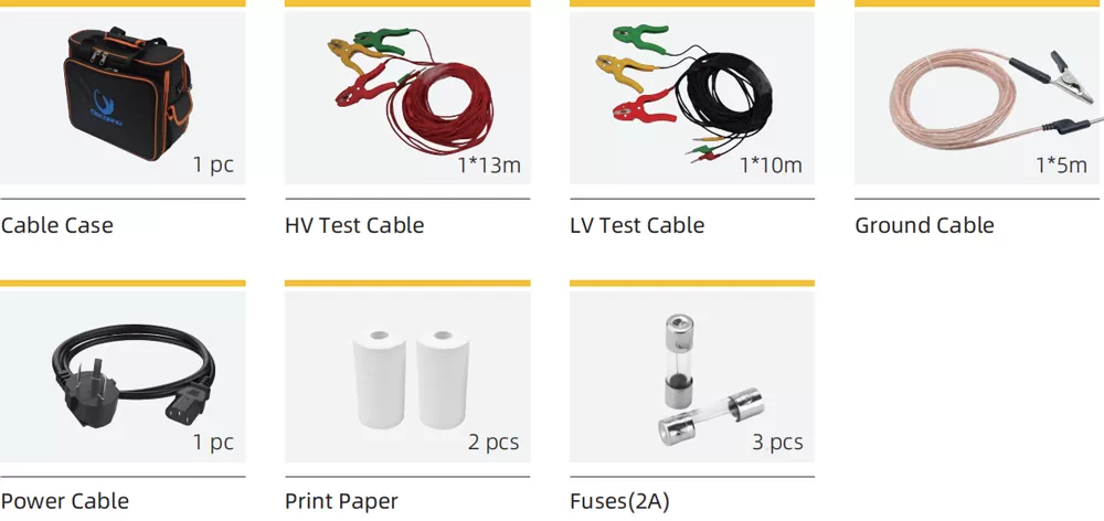
To learn more about the Transformer Turns Ratio Test, please refer to the following resources:
A conventional single-phase TTR tester excites one phase pair at a time, requiring three separate measurement cycles to test all phases of a three-phase transformer. The TRT-20 applies test voltage to all three phases simultaneously and measures all three ratios in one cycle. This 3-phase approach provides three key advantages:
Speed: Testing is up to 5× faster than sequential single-phase measurements. For a service company testing 10+ transformers per day, this translates to significantly more tests per shift.
Vector group recognition: The TRT-20 automatically identifies the transformer's vector group (e.g., Dyn11, YNd5, Yyn0) directly from the 3-phase measurement. With a single-phase tester, you must perform a separate multi-step sequence and manually look up the vector group in a reference table — a process that is slower and introduces human interpretation risk.
Winding balance: All three phases are measured under identical excitation conditions, so the phase-to-phase % deviation is directly meaningful. A winding imbalance (e.g., shorted turns on one phase) that might be masked by sequential testing becomes immediately visible. Accuracy: ±0.1% of reading for ratios up to 500; ±0.2% for 500–3,000; ±0.3% for >3,000, meeting IEC 60076-1 requirements for all distribution and most power transformers.
Yes. With a ratio range of 0.9–10,000 and resolution down to 0.0001, the TRT-20 covers:
• Power transformers: typical ratios 1:1 to 400:1
• Distribution transformers: typical ratios 10:1 to 100:1
• Current transformers (CTs): ratios up to 10,000:1 (e.g., 5000 A / 1 A CT)
• Voltage transformers (PTs): ratios up to 10,000:1 (e.g., 110 kV / 110 V PT)
Important distinction: the TRT-20 performs accurate ratio, polarity, and phase shift measurement on CTs and PTs, but it does NOT perform the complete CT accuracy evaluation (excitation curve, ratio error %, phase displacement in arcminutes, ALF/FS, composite error) that a dedicated CT analyzer provides. For simple ratio verification of instrument transformers in the field, the TRT-20 is well-suited. For full CT calibration to IEC 61869-2, a dedicated CT analyzer is required.
The TRT-20's vector group recognition works by simultaneously measuring the amplitude ratios AND phase angles between all primary and secondary terminals during the 3-phase test. The vector group notation (e.g., Dyn11) describes:
• Primary winding connection: D = delta, Y = wye (star), Z = zigzag
• Secondary winding connection: same notation
• Number: the phase displacement between primary and secondary, expressed as clock hours (1 = 30°, so Dyn11 = 330° phase lag of secondary relative to primary)
The TRT-20 measures the actual phase angles between the injected primary voltages and the induced secondary voltages, then matches the pattern against the IEC 60076-1 vector group table. The result is displayed directly on the color screen (e.g., 'Dyn11 confirmed'). This is particularly valuable when testing transformers with missing, damaged, or illegible nameplates — a common scenario in brownfield substations. Connecting a transformer with an incorrectly identified vector group to the grid can cause phase rotation errors, circulating currents between paralleled transformers, and protection relay misoperation.
Please tell us your testing requirements, application scenarios or project details, and our engineers will recommend the solution and quotation that suits you within 24 hours.