English
  日本語
日本語  한국어
한국어  français
  Deutsch
  русский
  português
  العربية





What are you looking for?

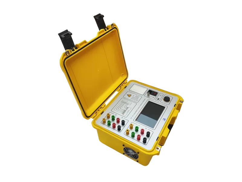
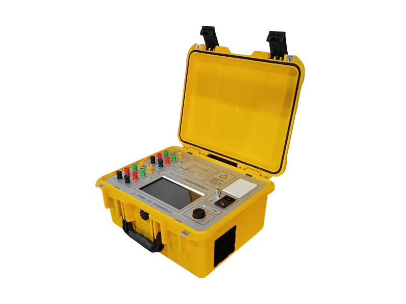
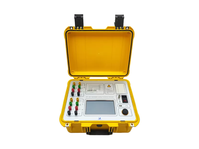
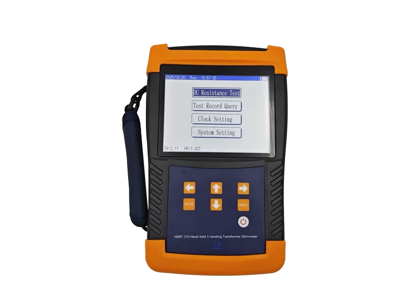
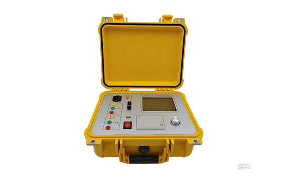
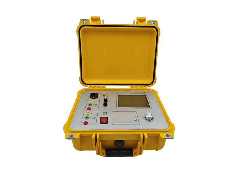
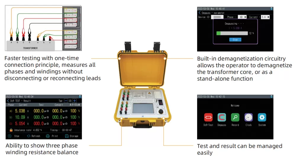
The DRT3XXL series of automated six-winding transformer ohmmeters delivers full eight-terminal resistance measurement capability. This electrical integrity tester is designed to save you time by testing all normal six windings without having to disconnect and reconnect leads during testing. Also, the simultaneous winding magnetization (SWM) method gives fast and reliable measurements, even on large transformers with delta configuration on the low voltage side.
Built-in auto-demagnetization
Built-in printer
DC test current up to 20A or 40A (optional)
| Test model | Single phase or Three phase | |
| Test current | Single Phase:20A,10A,5A,1A,0.1A,10mA,<1mA | |
| Test Range | Three Phase:10A+10A,5A+5A,1A+1A,0.1A+0.1A | |
| Single Phase: | Three Phase: | |
| 20A(0.5mQ~1Ω) | ||
| 10A(1.0mΩ~2Ω) | 10A+10A(0.5mΩ~0.8Ω) | |
| 5 A(10mΩ~4Ω) | 5A+5A(10 mΩ~1.6 Ω) | |
| 1A(0.1Ω~20Ω) | ||
| 0.1A(2.00~100Ω) | 1A+1A(0.1Ω~8.0 Ω) | |
| 10mA(50Ω~2kΩ) | 0.1A+0.1A(2.0Ω~80 Ω) | |
| <1mA(500Ω~25kΩ) | ||
| Accuracy | ±0.2%rdg+2digt | |
| Power Supply | 200~240VAC,50/60Hz | |
| Temperature | -10℃~50℃ | |
| Humidity | ≤90%,No dew | |
| Dimension | 9kg | |
| Weight | 400×315×223mm | |
Perform field testing of CT, PT, power transformer windings and their associated tap changers, and motors/generators.
Verify factory winding resistance test results.
Perform factory heat run tests.
Diagnose and pinpoint problems such as the presence of defects in transformers, such as loose connections, and check the operation of on-load tap changers.
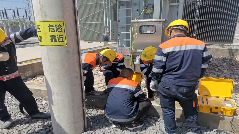
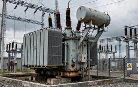
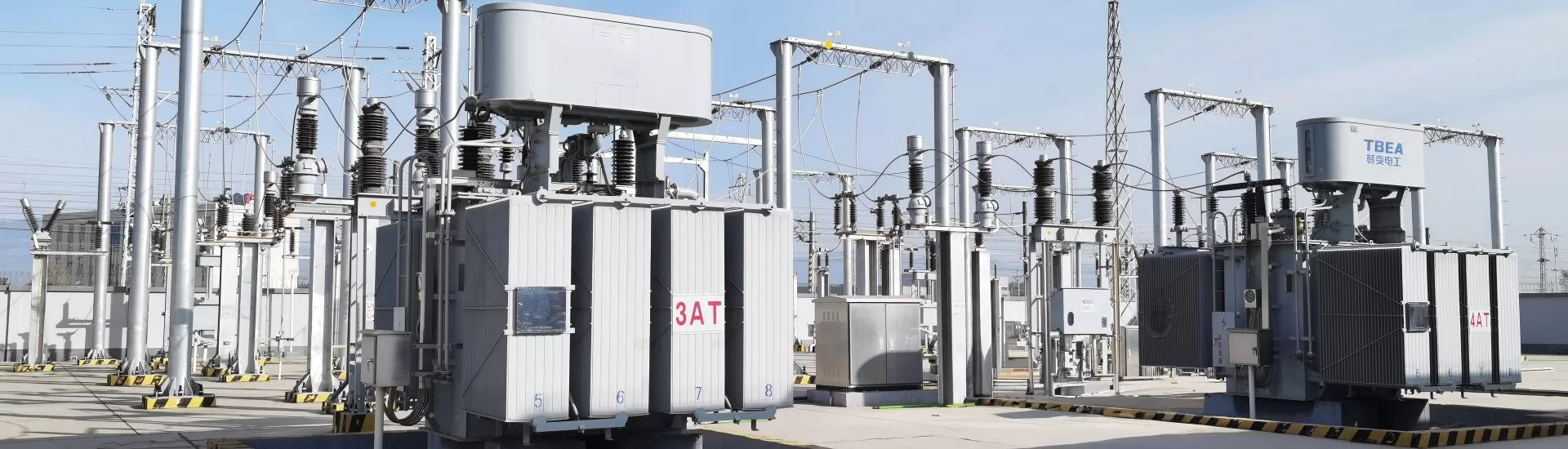
Transformer winding resistance testing is one of the most important diagnostic procedures used during transformer manufacturing, commissioning, and maintenance. The test helps identify loose connections, shorted turns, defective tap changers, and winding deformation before serious failures occur.
Regular winding resistance testing improves transformer reliability, reduces maintenance costs, and ensures compliance with international testing standards.
To learn more about the transformer winding resistance measurement, please refer to the following resources:
A traditional DC winding resistance tester uses a 2-lead or 4-lead (Kelvin) connection and measures one winding at a time. To test a typical two-winding three-phase transformer (e.g., Dyn11), you need to measure 3 HV windings + 3 LV windings = 6 independent measurements. Each measurement cycle involves: connecting the leads to the winding → waiting for current stabilization in the highly inductive winding (3–8 minutes per winding for large units) → recording the value → disconnecting → moving to the next winding. Total test time for a 40 MVA transformer using a single-channel instrument is typically 45–60 minutes. The DRT-320L changes this completely with its eight-terminal, six-winding architecture:
Connect all HV and LV leads once at the beginning of the test
The instrument internally sequences through all six windings automatically
The Simultaneous Winding Magnetization (SWM) method energizes all three phases of a winding group together, dramatically reducing stabilization time on delta-connected LV windings — the most time-consuming case in conventional testing
Total test time for the same 40 MVA transformer: approximately 8–12 minutes
Beyond speed, the one-time connection improves safety by reducing the number of times the operator must climb onto the transformer to swap leads.
SWM is a technique where all three phases of a transformer winding group are energized simultaneously rather than sequentially. In a delta-connected LV winding, the three phases are electrically connected in a closed loop. When you inject DC current into only one phase, the current must distribute through the entire delta loop, and the changing flux induces circulating currents that take a long time to decay to a stable DC measurement condition. This is why delta windings are notoriously slow to test with single-channel ohmmeters.SWM solves this by energizing all three phases together:
The magnetic flux in the core builds uniformly across all three limbs
Circulating currents are minimized because all phases reach saturation at approximately the same rate
The core saturates faster, and the current stabilizes to a clean DC value sooner
The DRT-320L applies SWM at 10 A + 10 A (three-phase mode) or 5 A + 5 A, selectable based on the transformer size. For single-phase measurements (e.g., individual winding or tap changer contact resistance), the instrument operates at up to 20 A.
Injecting DC current into a transformer winding — as all DC resistance testers do — magnetizes the iron core. When the test current is removed, the core retains residual magnetism (remanence). This residual flux can cause:
① Transformer inrush current: when the transformer is re-energized after testing, the residual flux combined with the AC energization flux can drive the core deep into saturation on the first half-cycle, producing an inrush current up to 10–20× rated current — potentially tripping protection relays or causing mechanical winding stress.
② Measurement interference: a magnetized core shifts the operating point on the BH curve, which can affect subsequent test results — especially excitation current, turns ratio (if the core is partially saturated), and SFRA measurements.
③ Protection CT accuracy: if the transformer's bushing CTs are also tested with DC and not demagnetized, the residual flux can cause the CT to saturate prematurely during faults, leading to protection misoperation.
The DRT-320L's built-in automatic demagnetization cycle applies a polarity-reversing, gradually decreasing AC-DC current sequence after the resistance measurement completes. This walks the residual flux back to near zero — fully automated, no operator action required. The demagnetization function can also be run as a standalone operation if you need to demagnetize a core that was previously tested with another instrument.
Please tell us your testing requirements, application scenarios or project details, and our engineers will recommend the solution and quotation that suits you within 24 hours.