English
  日本語
日本語  한국어
한국어  français
  Deutsch
  русский
  português
  العربية




What are you looking for?

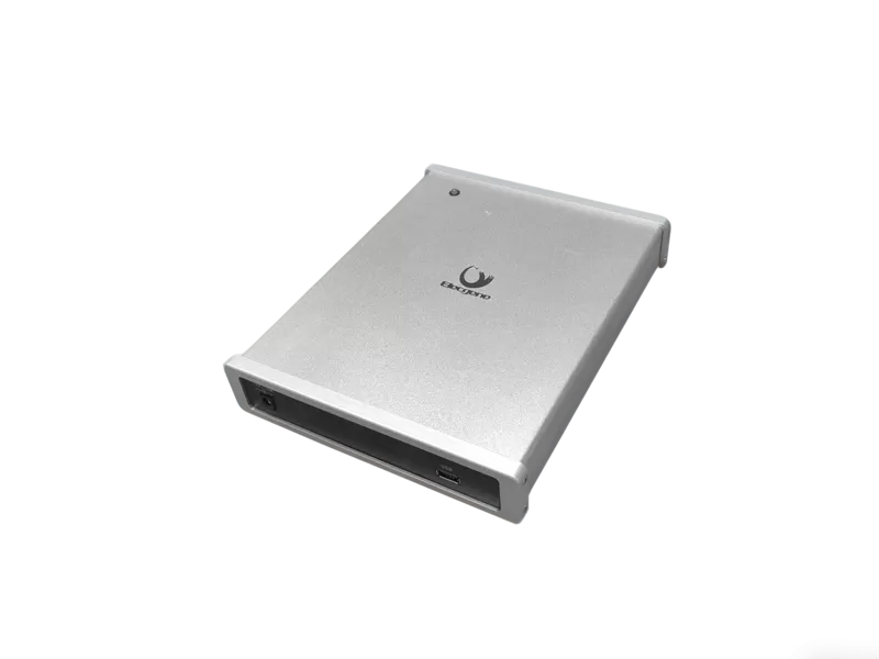
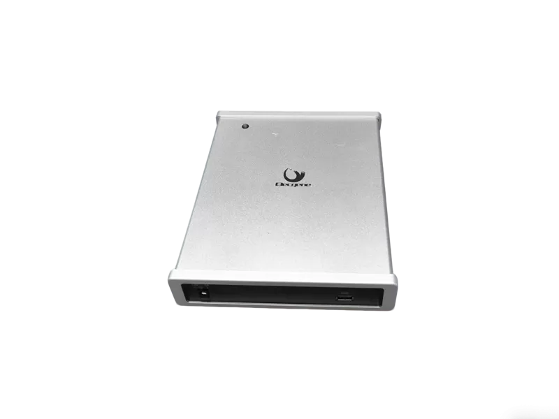
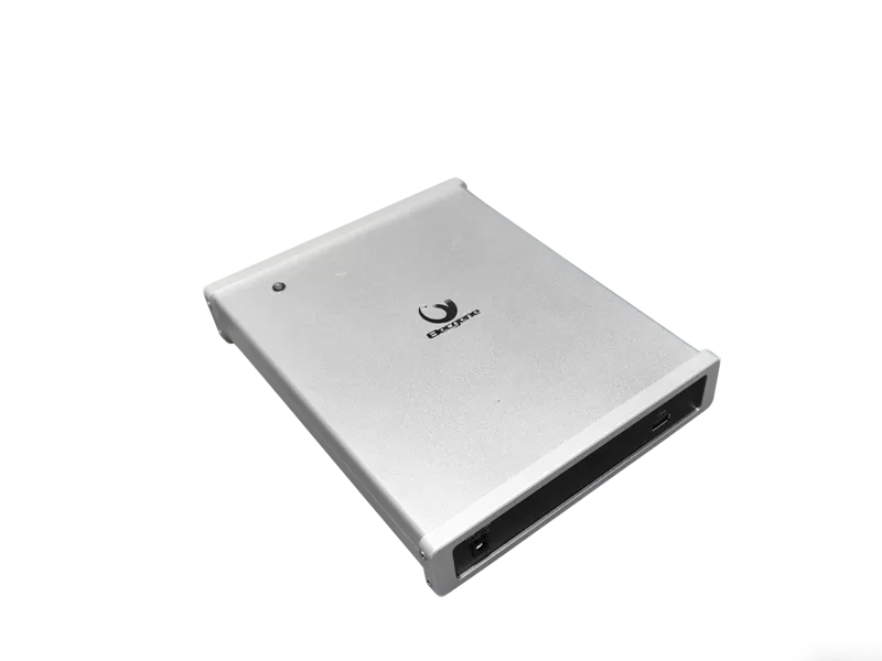
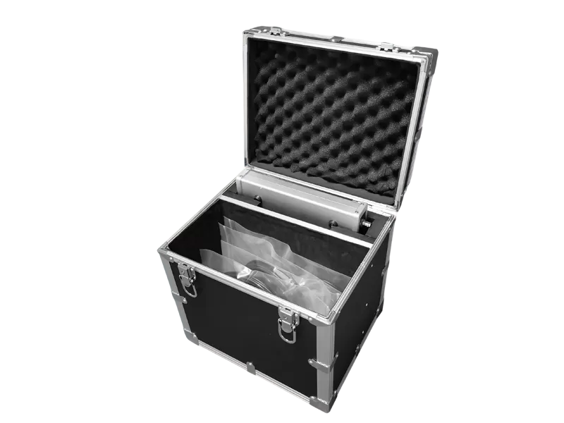
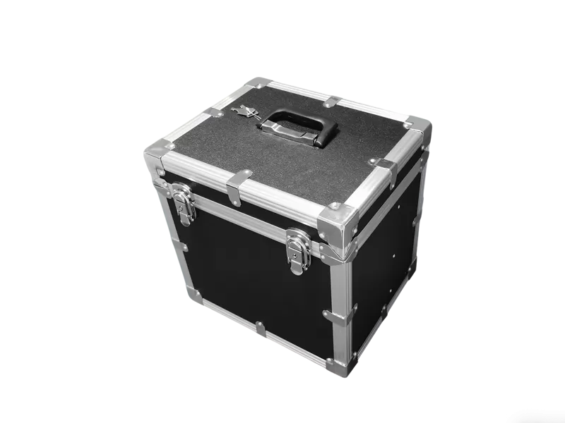
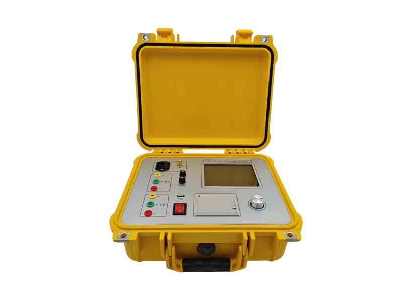
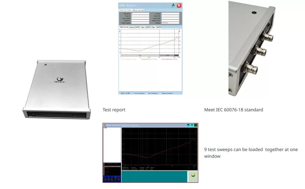
Deformation of transformer windings is measured with frequency response analysis method according to national standard DL/T911-2016/IEC60076-18 for electric power industry, i.e. detect amplitude-frequency response characteristic of each transformer winding and make vertical or horizontal comparison of the detection result to judge possible deformation of the transformer winding based on change of amplitude-frequency response characteristics. Mini-WDT uses SFRA method to assess whether or not a transformer has been subject to mechanical damage. It's a very portable power transformer testing tool, making it very convenient to connect to external PC.
Meet IEC 60076-18 standard
Portable and light-weight for easy use
Analysis software allows further diagnostics
Reproducible results thanks to innovative connection technique
Mini-WDT detects transformer problems such as:
Winding deformations and displacements
Shorted turns and open windings
Broken clamping structures
Core connection problems
Partial winding collapse
Faulty core grounds
Core movements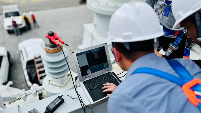
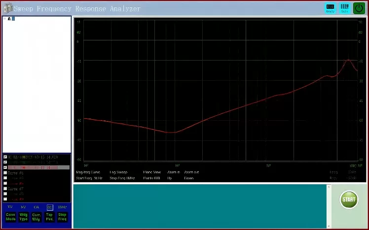
Mini-WDT injects a sinusoidal excitation voltage with a continuously increasing frequency into one end of the transformer winding and measures the signal returning from the other end. Due to a direct measurement in the frequency domain, no additional data processing is required. The comparison of input and output signals generates a unique frequency response, which can be compared with reference data. Thereby, deviations can indicate changes of internal components. These deviations can be directly related to different sections of the frequency range and they can be discerned from each other.
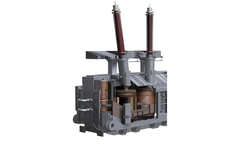
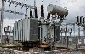
Transformer windings may experience deformation during transportation, short-circuit events, seismic activity, or mechanical stress. These internal changes are often invisible during routine inspections. SFRA testing provides a non-invasive method for identifying winding displacement, core movement, clamping failures, and other mechanical defects before they lead to transformer failure.
| Output Voltage | Vpp-25V automatic adjustment during test |
| Input Impedance | 1MΩ (Built-in 50Ω matching resistance in the test channel) |
| Frequency Sweep Range | 10Hz-2MHz (Customizable up to 30MHz) |
| Output Impedance | 50Ω |
| Measuring Dynamic Range | -100dB~20dB |
| Frequency Accuracy | 0.00001 |
| Input Power | 100-240V AC, 50/60 Hz |
| Environmental Conditions | Operating temperature : -10℃~50℃ Humidity :≤90% |
| Net Size | 238×184×40mm |
| Net Weight | 2.45kg |
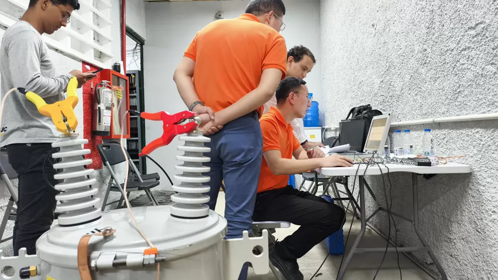
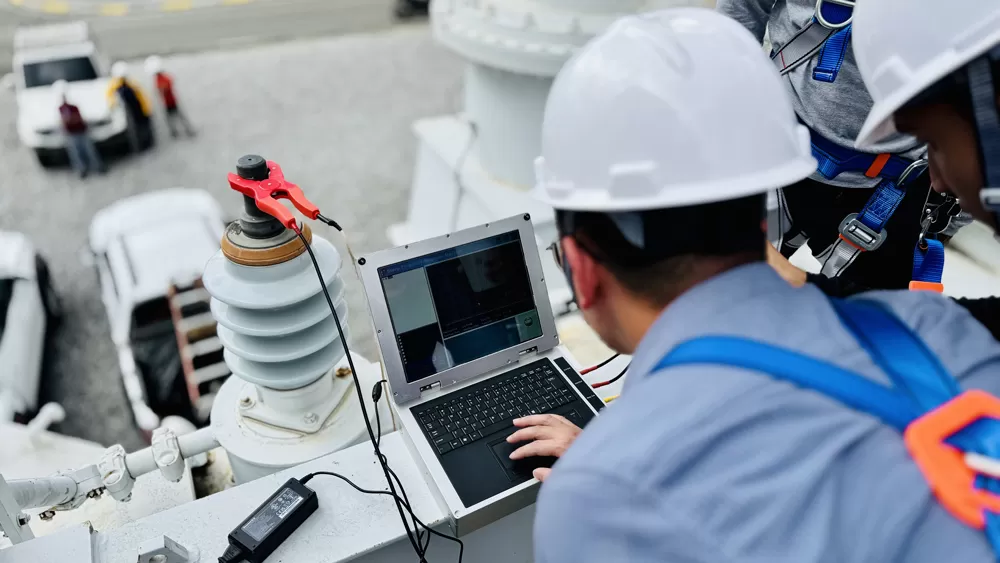
SFRA testing is commonly recommended:
After Transformer Transportation
Transportation vibration may cause winding movement.
After Short-Circuit Events
High fault currents can mechanically stress transformer windings.
During Commissioning
Establishes a baseline transformer fingerprint.
During Scheduled Maintenance
Allows trend analysis and condition monitoring.
A transformer winding can be modeled as a distributed RLC network — each turn has resistance (R), inductance (L) that depends on its physical position relative to the core and other windings, and capacitance (C) between adjacent turns, between winding layers, and between the winding and the grounded core/tank.
A turns ratio test verifies the electrical turns count. A DC resistance test verifies the electrical continuity. Both are 'electrical' tests — they pass or fail based on whether the copper path is intact. SFRA detects mechanical changes. If a winding shifts by even a few millimeters — due to a through-fault electromagnetic force, transportation damage, or seismic event — its distributed L and C values change, and the frequency response signature shifts. The winding may still have the correct ratio and normal DC resistance, but its mechanical integrity is compromised. By the time the ratio or resistance test fails, the transformer is typically already in catastrophic condition.
SFRA can detect:
• Winding deformation (radial buckling, axial collapse, hoop buckling)
• Winding displacement (movement relative to core)
• Shorted turns (turn-to-turn insulation failure)
• Broken or loosened clamping structures
• Partial winding collapse
• Faulty core grounds
• Core movement or lamination damage
The Mini-WDT performs SFRA as defined in IEC 60076-18 and DL/T 911-2016:Measurement principle:
① A sinusoidal excitation voltage (up to 25 Vpp, automatically adjusting during the sweep) is injected into one end of the transformer winding
② The signal returning from the other end of the winding is measured
③ The transfer function H(f) = Vout(f) / Vin(f) is computed — plotted as magnitude (dB) and phase (degrees) versus frequency
④ The resulting frequency response curve is compared against a reference: a previous test of the same unit (time-based), a sister unit or identical design (type-based), or adjacent phases of the same transformer (phase-based)
Frequency sweep range: 10 Hz – 2 MHz (custom-extendable to 30 MHz on request)
Frequency accuracy: 0.00001 Hz
Measuring dynamic range: -100 dB to +20 dB
Output impedance: 50 Ω
Input impedance: 1 MΩ (built-in 50 Ω matching resistance in the test channel)
What each frequency band reveals:
• < 2 kHz: core magnetization, core ground integrity, residual magnetism effects
• 2 kHz – 20 kHz: bulk winding movement, overall inductance changes
• 20 kHz – 200 kHz: inter-winding displacement, clamping structure changes
• 200 kHz – 2 MHz: turn-to-turn geometry, local deformations, lead and bushing effects
The standard sweep range (10 Hz – 2 MHz) conforms to IEC 60076-18 and covers all standard diagnostic bands.
SFRA interpretation has historically been criticized as subjective — different engineers can look at the same two curves and reach different conclusions. The Mini-WDT software addresses this by implementing the quantitative assessment methods defined in international standards:
① Correlation Coefficient (CC) analysis per DL/T 911-2016: Each frequency sub-band is assigned a correlation coefficient (0–1) comparing the test trace to the reference trace.
• CC > 0.99: normal (no significant deformation)
• CC 0.90 – 0.99: minor change — investigate further
• CC < 0.90: significant deformation — do not re-energize without physical inspection
② Three IEC 60076-18 comparison methods:
• Time-based: same unit, different test date (fingerprint comparison)
• Type-based: identical design, different unit (sister transformer comparison)
• Phase-based: different phases of the same transformer
③ Multi-curve overlay: up to 9 test sweeps can be loaded simultaneously, displayed in different colors, allowing visual comparison across phases, across time, and against the factory fingerprint — all on one screen.
④ Automated assessment report: the software generates a numeric summary with CC values per frequency band and an overall pass/caution/fail recommendation. The engineer can review each CC value and the overlaid curves before making the final judgment — the software provides objective indicators, not a black-box decision.
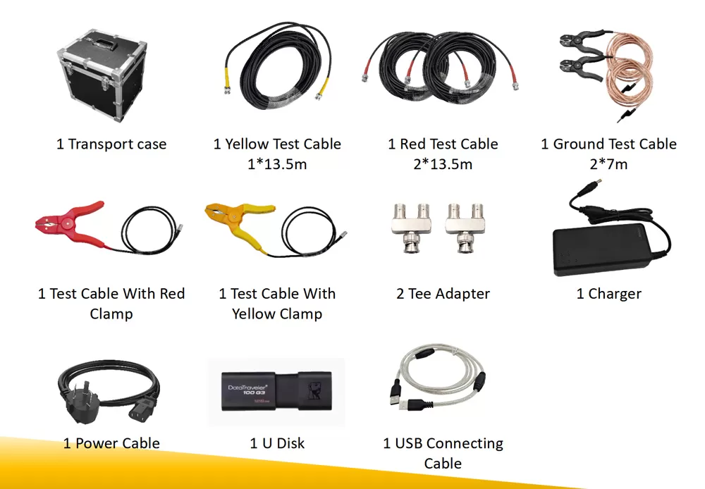
The Mini-WDT achieves its ultra-portable form factor through a deliberate architectural choice: the instrument handles only precision signal generation and acquisition; all processing, display, analysis, and storage are performed on the connected PC via the included software.
Inside the Mini-WDT (2.45 kg, 238 × 184 × 40 mm):
• Precision DDS (Direct Digital Synthesis) signal generator: 10 Hz – 2 MHz, 0.00001 Hz accuracy
• High-impedance measurement input: 1 MΩ, with built-in 50 Ω matching
• Amplitude auto-adjustment: output voltage automatically adapts during sweep for optimal SNR
• USB interface for PC connection and power
On the PC (software):
• FFT computation and signal processing
• Transfer function calculation and curve display
• Multi-curve overlay and comparison
• CC calculation per IEC/DLT standards
• Automated report generation
• Data storage and archive management
This architecture has practical advantages:
• The instrument is small enough to fit in a laptop bag — truly carry-on portable for air travel
• The PC screen is larger than any embedded instrument display, making multi-curve comparison clearer
• Test data lives on your laptop, not in proprietary internal storage — easier to back up and share
• Software updates are simple downloads, no instrument firmware flashing required
The trade-off: you must have a PC to operate the instrument. It is not a standalone device. For users who prefer a fully self-contained instrument with an integrated screen, this is a consideration.
Please tell us your testing requirements, application scenarios or project details, and our engineers will recommend the solution and quotation that suits you within 24 hours.