PART 1: Inspection Purpose
According to relevant regulations and provisions such as the "Technical Specifications for Live Detection of Power Equipment (Trial)" and the "State Grid Corporation Substation Detection Management Regulations (Trial) State Grid (Operation and Inspection 3) 829-2017", the power industry conducts non-stop monitoring, detection, and fault diagnosis of the operating status of electrical equipment such as substations and lines through inspections and patrols. This is to ensure the safe and stable operation of electrical equipment and to arrange maintenance work timely and reasonably.
PART 2: Inspection Case
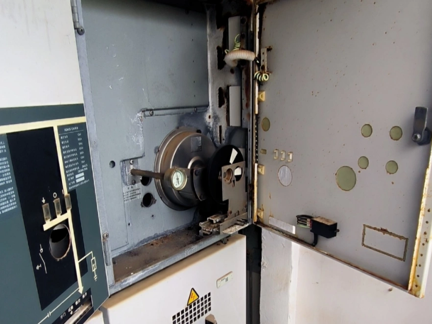
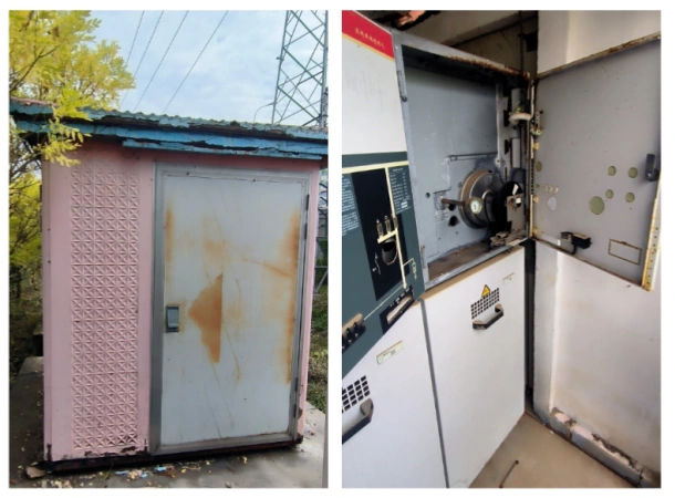
An important meeting was recently held in a certain location, requiring advanced inspection of the venue's power supply lines to eliminate hidden dangers and ensure normal power operation. During the patrol inspection, a suspected partial discharge signal was found in a 10kV Ring Main Unit (RMU). Therefore, an acoustic imager was deployed for discharge detection and localization to troubleshoot and inspect several important power supply lines.
PART 3: Inspection Method
When a defect occurs, it may be accompanied by different phenomena such as heat generation, mechanical vibration, electromagnetic waves, and sound waves. Currently, the power industry mainly relies on infrared detection methods for line inspections. However, some fault points exhibit obvious discharge phenomena without generating heat. Therefore, combining infrared detection with partial discharge (PD) detection forms a more comprehensive detection method.
PART 4: Equipment Used This Time
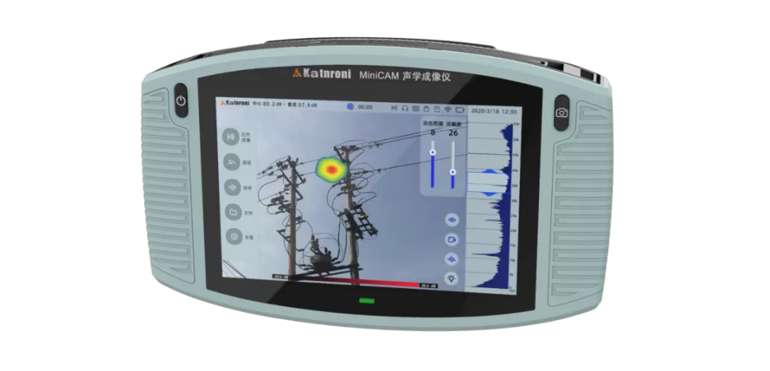
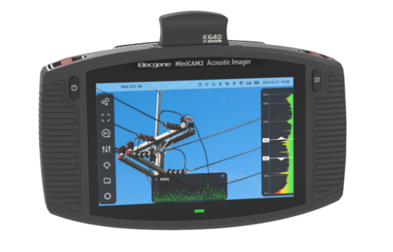
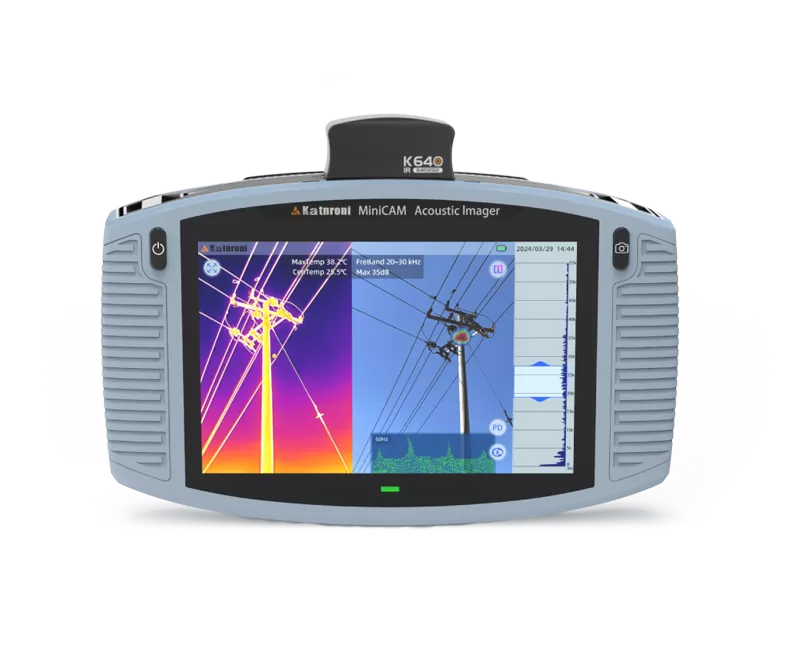
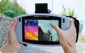
MiniCAM Acoustic Imager: It utilizes sound time delay and sound field reconstruction to locate sound and combine it with images, achieving the imaging and positioning of sound sources (including discharge ultrasonic waves, sound waves, etc.). The equipment is lightweight and portable, featuring 128 microphone sensors, a 7-inch full-color touch screen, and weighing approximately 1.3kg. It is simple to operate and fast in detection. It can discover abnormal sound points and discharge points of target equipment from a long distance, non-contact, and without power interruption, achieving the goals of live detection, defect early warning, and targeted maintenance. An external infrared module can realize the simultaneous display of partial discharge and infrared imaging on the same screen.
PART 5: Defect Analysis Report
1. Severe Discharge in XX 10kV Ring Main Unit (RMU)
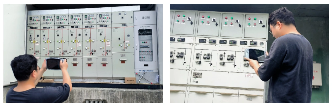
Upon arriving at the RMU suspected of partial discharge, the acoustic imager was used for detection, immediately revealing a stable signal point. Detection was performed from different angles on the front and sides of the RMU, and the signal imaging stabilized in the middle position of the RMU on the screen.
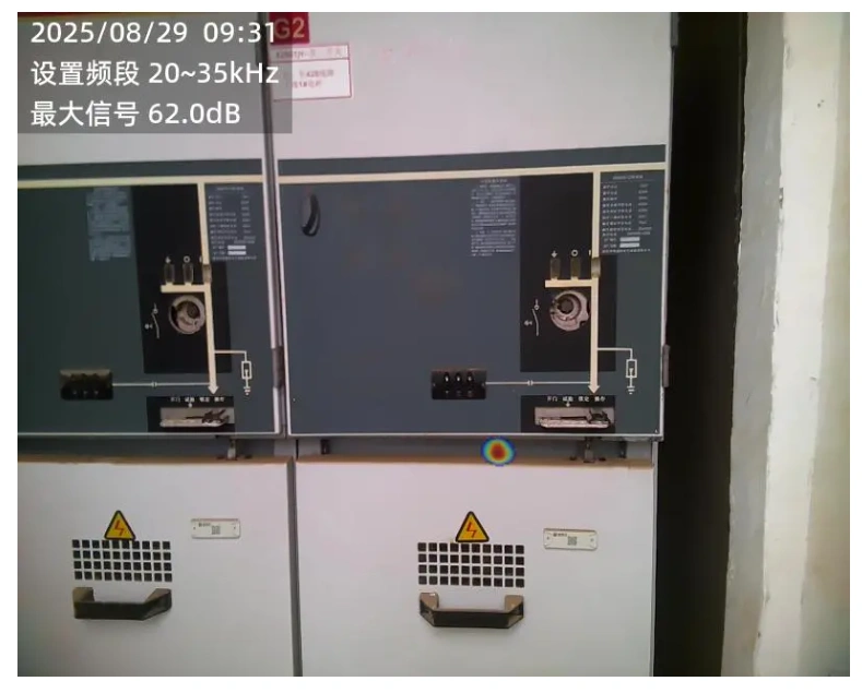
The signal imaging point on the screen did not change with the tester's position, and the signal was stable, ruling out external noise interference and confirming it as a true abnormal signal.
This signal appears at the gap position in the middle of the cabinet, which conforms to the basic characteristic of internal cabinet discharge: the signal transmits outwards through gaps. The maximum detected amplitude of the abnormal signal is about 61dB, judged to be a severe discharge that requires immediate handling.
2. Slight Discharge of Insulators and Drop-out Fuses on XX 10kV Overhead Line
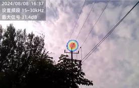
Discharge signals appeared at the positions of overhead line insulators and drop-out fuses.
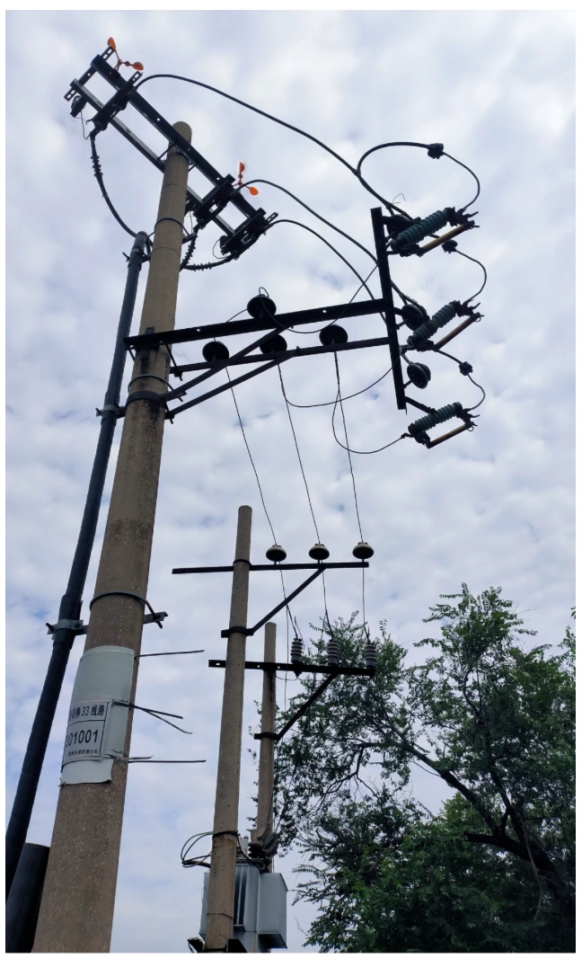
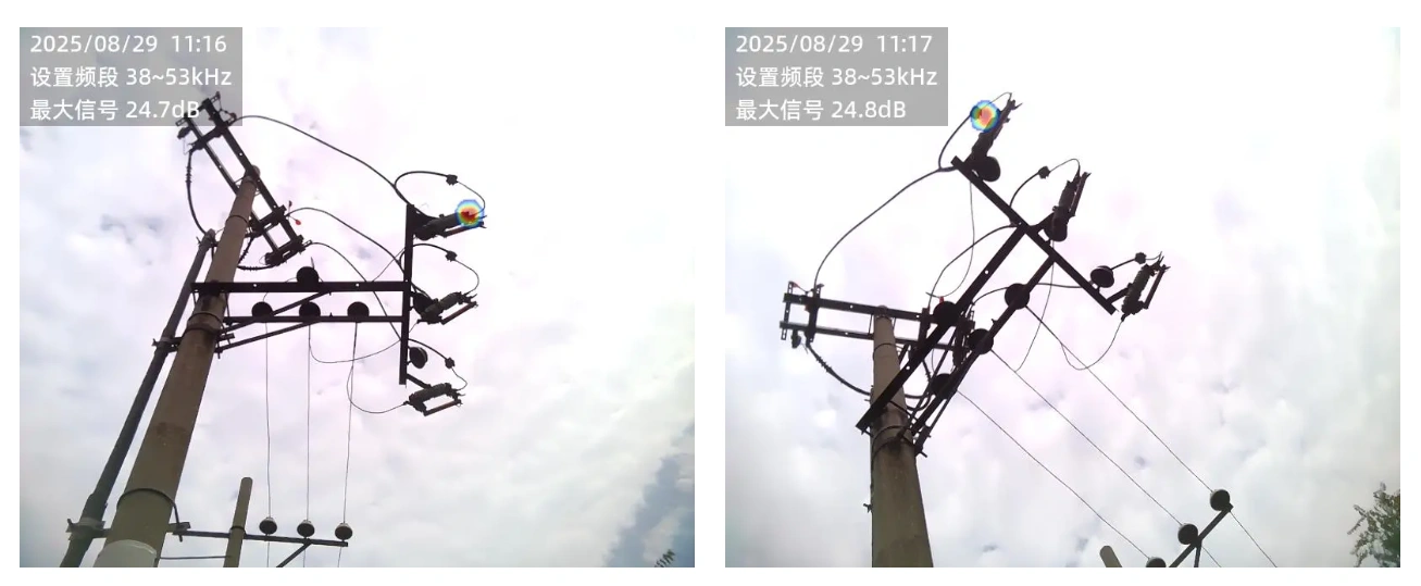
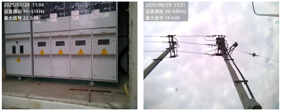
The discharge signal at the drop-out fuse position is stable with a relatively small amplitude; the maximum detected signal amplitude is 25dB, classifying it as a slight discharge. The discharge signal appears at the contact position. It is suspected that loose contact or contact oxidation is causing the partial discharge. It is recommended to reclose the fuse a few times and observe/measure again.
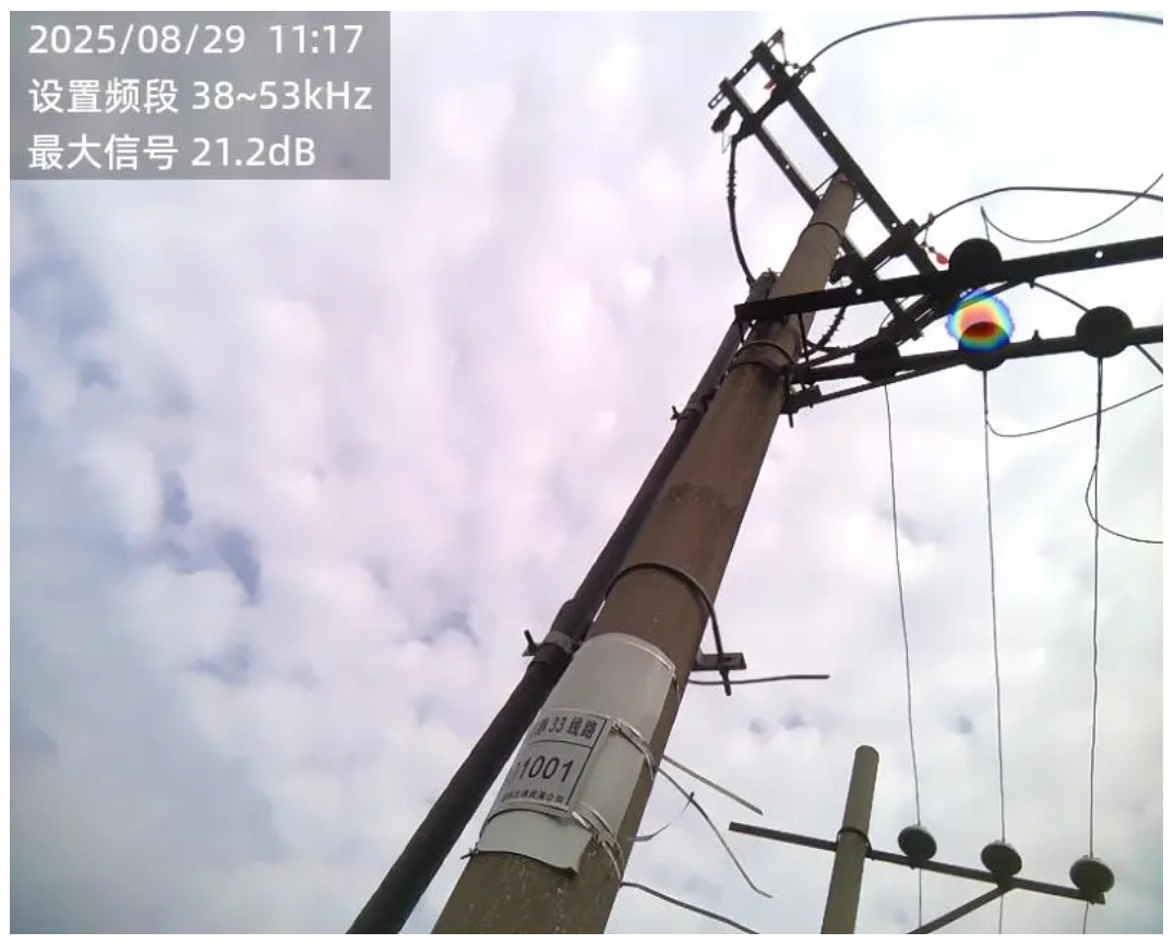
The middle phase insulator is discharging with a maximum measured amplitude of 22dB. The low signal amplitude indicates a slight discharge, and continuous monitoring is recommended.
The amplitudes of the two discharge signals at this location are relatively low, both categorized as slight discharges. Under such circumstances, it is recommended to increase the frequency of reviewing online monitoring data or increase the number of live detections to shorten the inspection cycle. Record the values from each detection, monitor the trend changes, analyze the reasons for the trend development, and prepare for possible subsequent maintenance.
PART 6: On-site Inspection Situation
For the three tested lines, excluding the two locations mentioned above, no discharge signals were found in other RMUs and overhead line towers.

 English
  日本語
日本語  한국어
한국어  français
  Deutsch
  русский
  português
  العربية