Leakage current during a hipot test should be interpreted by examining how the current changes with voltage and time—not by judging one isolated reading. A relatively high but stable current may be normal when testing a capacitive object with AC voltage. During a DC hipot test, a high initial current that gradually decreases may mainly represent capacitive charging and dielectric absorption. By contrast, current that continues to rise, changes abruptly or becomes unstable at a constant voltage may indicate contamination, surface tracking, corona, flashover or developing insulation breakdown.
There is no universal leakage-current limit that applies to every cable, transformer, motor, switchgear assembly or electrical component. The correct acceptance criteria must come from the equipment standard, manufacturer specification, approved test procedure and historical test data.
Elecgene provides hipot testers for AC withstand testing, DC withstand testing and leakage-current measurement across different voltage, current and load requirements.
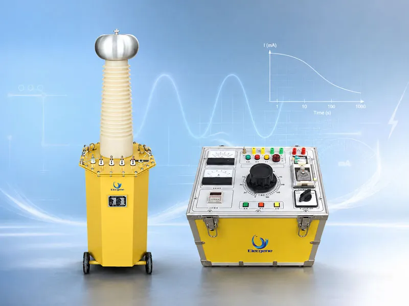
What Does Leakage Current Mean During a Hipot Test?
Hipot leakage current is the current that flows through and over an insulation system while high test voltage is applied, but the displayed current may also include charging, polarization and capacitive components.
A hipot tester applies voltage between conductive parts separated by insulation. The instrument monitors the resulting current to determine whether the insulation can withstand the specified voltage without breakdown, flashover or excessive current.
The meaning of the displayed current depends heavily on whether AC or DC voltage is being applied.
Current Components During a DC Hipot Test
During a DC test, the total measured current can be described as:
IDC = Icharging + Iabsorption + Isurface + Iconduction
The components behave differently over time.
Capacitive charging current appears immediately after voltage is applied or increased. It is used to charge the electrical capacitance of the test object and normally falls quickly after the voltage stabilizes.
Dielectric absorption current, also called polarization current, results from the gradual alignment and movement of charge within the insulation. It normally decreases more slowly than capacitive charging current.
Surface leakage current flows over the outside surface of insulation. Moisture, dust, salts, oil and other contamination can increase this component.
Conduction current flows through the insulation material itself. After charging and absorption currents have substantially decreased, conduction and surface leakage make up much of the remaining steady current.
For example, if a DC hipot tester applies 50 kV and the stabilized measured current is 5 μA, the apparent resistance calculated from voltage divided by current is:
R = 50,000 V ÷ 0.000005 A = 10 GΩ
This calculation is only meaningful after transient current has decreased and when the measurement circuit is known to include the intended insulation path. It is not, by itself, a pass-or-fail criterion.
Current Components During an AC Hipot Test
During an AC test, the measured current normally includes a continuous capacitive component because the test voltage reverses polarity during every cycle.
The approximate capacitive current is:
IC = 2πfCV
Where:
IC is capacitive current;
f is test frequency;
C is test-object capacitance;
V is the applied RMS voltage.
Consider an insulation system with a capacitance of 0.01 μF tested at 50 kV and 50 Hz:
IC = 2π × 50 × 0.01 μF × 50 kV ≈ 0.157 A
The object therefore requires approximately 157 mA of capacitive current, before additional dielectric-loss or leakage components are considered. The corresponding reactive capacity is approximately:
50 kV × 0.157 A = 7.85 kVA
This example shows why a numerically high AC current does not automatically indicate poor insulation. For high-capacitance equipment, most of the current may be normal capacitive current rather than damaging conduction leakage.
How Should Hipot Leakage Current Patterns Be Interpreted?
A leakage-current pattern is interpreted by observing its direction, stability, rate of change and relationship to test voltage, time and comparable measurements.
The most useful diagnostic information usually comes from a current-versus-time or current-versus-voltage trend.
| Leakage-Current Pattern | Possible Interpretation | Recommended Response |
|---|
| High initial DC current that decreases smoothly | Capacitive charging and dielectric absorption | Allow the specified stabilization time before evaluating |
| Low and stable current at constant voltage | Insulation is withstanding the applied stress under current conditions | Compare with acceptance limits and historical results |
| Stable but unexpectedly high current | Surface contamination, moisture, incorrect connection or true conduction leakage | Check setup, clean surfaces and repeat according to procedure |
| Gradual nonlinear increase as voltage rises | Increasing conduction, multiple weak points or insulation deterioration | Compare with baseline and stop before current becomes excessive |
| Abrupt step increase | Corona, partial flashover, localized defect or breakdown development | Stop or reduce voltage according to the approved procedure |
| Unstable or fluctuating current | Intermittent discharge, moving test lead, poor connection, electrical noise or surface tracking | Halt the test and inspect the complete setup |
| Sudden drop toward zero | Lost output, open lead, protection trip or measurement-circuit failure | Do not interpret as a successful test; verify voltage and connections |
| One phase significantly different from the others | Phase-specific insulation condition or inconsistent setup | Repeat with identical leads, conditions and test sequence |
A Decreasing DC Current Is Often Expected
When a DC step voltage is applied, current normally begins at a higher value and decreases as the object charges and polarization progresses.
The reading should not be assessed too early. A cable, large winding or other high-capacitance object may require more stabilization time than a small component.
The test duration and reading time should remain consistent when comparing:
Stable Current Is More Meaningful Than the Initial Peak
A steady reading provides more information about conduction and surface leakage than the initial charging peak.
However, “stable” does not automatically mean “acceptable.” A stable current may still exceed the limit established by the equipment manufacturer or test standard.
The result should be evaluated alongside:
Applied voltage;
Test duration;
Temperature and humidity;
Insulation surface condition;
Test-object capacitance;
Previous test data;
Corresponding phases or similar equipment.
Rising or Stepped Current Requires Attention
Current that rises continuously at a constant voltage is generally more concerning than current that decreases and stabilizes.
The U.S. Bureau of Reclamation’s technical guidance on ramped DC stator insulation testing distinguishes gradual current increases from abrupt stepped changes. In that specific test context, it recommends stopping when a sharp increase of approximately 1–2 μA or more appears, or when unstable and repeated stepped increases occur. It also discusses stopping a slowly increasing test when total current becomes approximately three to six times the capacitive charging component. These figures apply to the particular rotating-machine ramp-test procedure described in the guide and must not be treated as universal limits for all hipot tests. See the targeted guidance in the U.S. Bureau of Reclamation’s insulation-testing manual.
The broader principle is more widely applicable: A sudden change in current slope can be more significant than the absolute current value.
Surface Leakage Can Produce a Misleading Result
Moisture and contamination can create a current path over the external insulation surface.
Possible sources include:
Wet cable terminations;
Dirty bushings;
Carbonized tracking marks;
Conductive dust;
Oil residue;
Incorrectly positioned test leads;
Insufficient separation from grounded structures.
Before concluding that internal insulation is defective, technicians should inspect and clean accessible surfaces, confirm creepage distances and repeat the measurement under controlled conditions.
AC vs DC Hipot Leakage Current: What Is the Difference?
AC hipot current is often dominated by continuous capacitive current, whereas stabilized DC hipot current more clearly reflects conduction and surface leakage after transient components decline.
| Interpretation Factor | AC Hipot Test | DC Hipot Test |
|---|
| Initial Current | Begins immediately and continues with each cycle | Often high initially because the object is charging |
| Capacitive Component | Continues throughout the test | Normally decreases after charging |
| Absorption Current | Included in dielectric behavior | Usually decreases gradually with time |
| Steady Leakage Visibility | Difficult to separate from total capacitive current | Easier to observe after stabilization |
| Current Source Requirement | Strongly affected by capacitance and frequency | Mainly affected by charging, leakage and output-current requirements |
| Current Trend of Concern | Excess current, instability or sudden change | Rising, stepped or unstable current after expected charging behavior |
| Stored Energy | Discharge is still required | Deliberate discharge and grounding are especially important |
| Acceptance Basis | Equipment standard, total current capacity and withstand result | Approved leakage limit, trend and withstand result |
The current displayed during an AC test should therefore not automatically be described as “leakage current.” In many test systems, it is more accurately the total output current supplied to the test object.
Selecting an AC or AC/DC Hipot System
The current capacity of the test system must exceed the expected normal test-object current with an appropriate engineering margin.
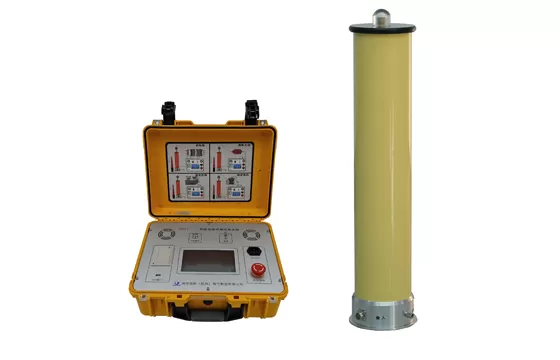
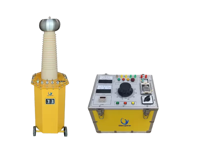
The Elecgene YTB-20 50 kV AC/70 kV DC high-voltage test system is available in 3, 5 and 10 kVA configurations. At 50 kV AC, the listed output-current ratings are 60, 100 and 200 mA respectively. With the optional DC rectifier, the corresponding listed DC current ratings are 20, 35 and 70 mA, and the rated duty cycle is five minutes on followed by fifteen minutes off.
Returning to the earlier example, a 0.01 μF object at 50 kV and 50 Hz requires approximately 157 mA of capacitive current. A 100 mA source would therefore be insufficient, while a 200 mA system might be considered only after accounting for dielectric-loss current, leakage, voltage stability and required operating margin.
Selecting a DC Hipot Tester
A portable DC tester should be selected according to:
Maximum required voltage;
Charging and steady leakage current;
Current-measurement accuracy;
Ripple;
Test duration;
Discharge procedure;
Test-object capacitance.
The Elecgene DHVT portable DC hipot tester includes standard 60, 120 and 200 kV configurations with current ratings from 2 to 20 mA, depending on the selected model. The published specifications list a ripple coefficient of no more than 0.5%, current-measurement accuracy of 0.5% plus one digit, and intermittent operation at rated load for up to 30 minutes.
The selected current range should be high enough to charge the test object and measure the expected leakage without repeatedly reaching the instrument’s protection limit.
Do Not Set the Trip Current Too Low
A trip threshold below the normal charging or capacitive current can stop a healthy test before the target voltage is reached.
Conversely, an unnecessarily high trip threshold may reduce protection against a developing failure.
The setting should account for:
Expected normal current;
Test-set measurement range;
Voltage ramp rate;
Test-object capacitance;
Approved leakage limit;
Protection response time;
Manufacturer instructions.
The latest IEC 60060-1:2025 covers dielectric testing with direct, alternating, impulse and combined voltages. It provides the general high-voltage test framework, while the equipment-specific standard or approved procedure must establish the applicable waveform, test level and acceptance requirements.
Conclusion: Interpret the Trend, Not Just the Number
A reliable hipot leakage-current assessment combines the absolute reading with its behavior over time, its response to increasing voltage and the known electrical characteristics of the test object.
A good result is not simply “the lowest current.” The expected pattern depends on the test method:
In a DC test, charging and absorption current should normally decline before stabilized leakage is evaluated.
In an AC test, substantial current may be required continuously to charge the test-object capacitance.
At constant voltage, a stable or decreasing pattern is generally less concerning than an accelerating, stepped or unstable increase.
Any result must still comply with the equipment standard, manufacturer data and approved procedure.
For repeatable trend analysis, record:
| Test Record | Why It Matters |
|---|
| Applied Voltage | Current cannot be compared without voltage |
| Current at Defined Times | Shows charging and stabilization behavior |
| Ramp Rate | Influences transient current |
| Test Duration | Supports valid historical comparison |
| Temperature and Humidity | Affect surface and volume leakage |
| Test Polarity | Important for repeat DC tests |
| Phase or Winding | Identifies localized differences |
| Test Lead Arrangement | Helps eliminate setup-related variation |
| Surface Condition | Documents contamination or moisture |
| Instrument and Range | Supports traceability |
High-voltage test objects may remain charged after testing. For example, a 0.01 μF object charged to 50 kV DC stores:
E = ½CV² = 12.5 joules
The U.S. Occupational Safety and Health Administration requires hazardous stored electrical energy to be released and states that capacitors and high-capacitance elements must be discharged, short-circuited and grounded when stored energy could endanger personnel. See OSHA 29 CFR 1910.333(b)(2)(ii)(C).
Elecgene recommends providing the test object, rated voltage, required test voltage, capacitance, expected leakage range, test duration and applicable standard when requesting a hipot tester recommendation.
FAQ
1. What is an acceptable leakage current during a hipot test?
There is no universal acceptable leakage-current value.
The limit depends on the test object, insulation design, applied voltage, waveform, test duration and applicable standard. Use the manufacturer’s specification or approved test procedure rather than a generic online value.
2. Is high leakage current always a sign of bad insulation?
No. During an AC test, a high total current may mainly be capacitive current. During the beginning of a DC test, high current may be caused by charging and dielectric absorption.
The current becomes more concerning when it exceeds the expected value, continues rising at constant voltage, changes abruptly or becomes unstable.
3. Why does DC hipot current decrease with time?
The current decreases because the test-object capacitance becomes charged and dielectric polarization gradually approaches equilibrium.
The remaining stabilized current is more closely associated with surface leakage and conduction through the insulation.
4. Why does AC hipot current remain high?
AC voltage continuously reverses polarity, so a capacitive test object must be charged and discharged during every cycle.
The capacitive current increases with frequency, capacitance and applied voltage according to IC = 2πfCV.
5. What causes leakage current to fluctuate during a test?
Possible causes include intermittent discharge, corona, surface tracking, moisture, unstable test leads, poor grounding, electrical interference or a developing insulation fault.
Stop the test and inspect the setup when fluctuations are unexpected or increase with voltage.
6. Should a test be stopped when leakage current starts rising?
A small predictable increase as voltage rises may be normal. A sudden step, accelerating slope or unstable increase is more concerning.
Follow the equipment-specific stopping criteria and approved procedure. Do not continue solely because the tester has not yet reached its automatic trip threshold.

 English
  日本語
日本語  한국어
한국어  français
  Deutsch
  русский
  português
  العربية