AC and DC hipot testing are both dielectric withstand methods, but they apply different electrical stresses and require different test equipment. AC hipot testing applies alternating voltage and is commonly selected when the insulation must be evaluated under an AC stress similar to its operating waveform. DC hipot testing applies unidirectional voltage and is useful when an approved procedure requires DC withstand testing or stable leakage-current observation.
Neither method is automatically better. The correct choice depends on the test object, insulation design, rated voltage, capacitance, applicable standard, test purpose and available equipment. For power utilities, manufacturers and electrical service companies, the first step is to review the complete range of Elecgene hipot testers and then match the AC or DC system to the actual test requirement.
How AC and DC Hipot Testing Work
AC hipot testing continuously reverses the polarity of the applied voltage, while DC hipot testing charges the insulation in one direction and maintains a unidirectional electrical field.
A hipot test applies a voltage above normal operating level between a conductor and ground, between windings or across another defined insulation barrier. The equipment passes when it withstands the specified voltage for the required duration without breakdown, flashover or unacceptable current.
The latest IEC 60060-1:2025 high-voltage test standard covers dielectric tests using direct voltage, alternating voltage, impulse voltage and combinations of these waveforms. It also makes clear that the relevant equipment standard or technical committee must determine the suitable test procedure.
How AC Hipot Testing Works
An AC hipot tester normally applies a sinusoidal voltage at power frequency or another approved test frequency. Because polarity changes every half-cycle, the insulation experiences repeated positive and negative electrical stress.
AC testing is commonly used for electrical equipment designed to operate on AC systems, including switchgear, instrument transformers, insulating materials, electrical components and selected cable or rotating-machine applications.
The current measured during an AC test is not only conduction leakage. It can include:
For capacitive test objects, the approximate charging current is:
I = 2πfCV
Where:
I is the AC capacitive current;
f is the test frequency;
C is the test-object capacitance;
V is the applied RMS voltage.
This relationship explains why long cables, GIS and large windings may require a high-capacity AC test source even when their actual insulation leakage is small.
How DC Hipot Testing Works
A DC hipot tester raises the voltage with one fixed polarity and holds it for the specified test period.
At the beginning of the test, the measured current can include:
Capacitive charging current
Dielectric absorption or polarization current
Surface leakage
Volume conduction current
The charging and absorption components normally decrease with time. The remaining steady current can provide useful leakage information when the test procedure and insulation system support DC evaluation.
DC testing can reduce the continuous charging-current demand placed on the high-voltage source. However, the test object stores electrical energy and may remain charged after the output is switched off. Controlled discharge and grounding are therefore essential.
AC Hipot Testing vs DC Hipot Testing: Key Differences
The most important difference between AC and DC hipot testing is not simply voltage polarity; it is how the waveform stresses the insulation, loads the test source and influences the measured current.
| Comparison | AC Hipot Testing | DC Hipot Testing |
|---|
| Applied Voltage | Alternating voltage with reversing polarity | Direct voltage with fixed polarity |
| Electrical Stress | Repeated positive and negative stress | Unidirectional electrical stress |
| Capacitive Current | Flows continuously | High initially, then normally decreases |
| Test-Set Capacity | Can be large for capacitive objects | Usually lower after charging |
| Current Interpretation | Includes capacitive and dielectric-loss components | Steady leakage is easier to observe after charging |
| Stored Charge After Test | Reduced through AC zero crossings, but discharge is still required | Can remain significant until deliberately discharged |
| Typical Equipment | Switchgear, components, instrument transformers and equipment with approved AC procedures | Surge arresters and equipment with approved DC procedures |
| Cable Application | Depends on cable type and applicable method | Must not be assumed suitable for every cable insulation |
| Main Equipment Selection Data | Voltage, capacitance, frequency, current and duty cycle | Voltage, output current, stored energy and duty cycle |
| Test Result | Withstand, flashover, breakdown and current behavior | Withstand, breakdown and time-dependent leakage behavior |
Why AC Test Equipment May Require More Capacity
Consider a test object with a capacitance of 0.1 μF tested at 50 kV RMS and 50 Hz.
Using the capacitive-current formula:
I = 2π × 50 × 0.1 μF × 50 kV ≈ 1.57 A
The reactive capacity is approximately:
50 kV × 1.57 A = 78.5 kVA
A conventional AC test transformer would therefore need to support a substantial capacitive load, even if the insulation has very little real leakage current.
This is why long cables and other high-capacitance assets may require a resonant AC system, lower-frequency method or another procedure authorized by the applicable standard.
Why DC Tests Require Careful Discharge
For the same 0.1 μF test object charged to 50 kV DC, the stored energy is:
E = ½CV² = 125 joules
That amount of stored energy can present a serious hazard. Larger capacitance or higher voltage increases stored energy rapidly because energy is proportional to the square of voltage.
AC and DC voltage values must therefore not be treated as directly interchangeable. Multiplying an AC test voltage by 1.414 only converts an ideal RMS sine-wave value to its peak value; it does not establish an equivalent DC withstand-test voltage or acceptance criterion.
How to Select the Right Hipot Test Method and Equipment
The correct hipot method is selected from the equipment standard, insulation system and test objective first, and from the available test-set voltage only after those requirements are known.
Start with the Test Object and Applicable Standard
Before choosing AC or DC, identify:
| Selection Information | Why It Matters |
|---|
| Test Object | Determines the expected insulation and load behavior |
| Rated Voltage | Establishes the equipment voltage class |
| Insulation Type | Influences field distribution and suitable waveform |
| Required Test Voltage | Determines the high-voltage output rating |
| Test Duration | Affects heating, duty cycle and stored energy |
| Capacitance | Strongly affects AC source capacity |
| Leakage-Current Requirement | Determines DC measuring range and trip setting |
| Test Environment | Influences portability, grounding and safety design |
| Applicable Standard | Defines the permitted method and acceptance criteria |
| Previous Test Data | Supports consistent trend comparison |
For shielded power cables rated 5 kV and above, IEEE 400-2023 describes multiple available field test methods and their advantages, disadvantages and suggested applications. This is important because cable method selection depends on insulation construction and test purpose rather than one universal AC-or-DC rule.
DC should not be selected for every cable merely because the test equipment is smaller. The approved method may instead require power-frequency AC, resonant AC, very-low-frequency AC or another diagnostic technique.
Select AC Hipot Testing When
AC testing is generally considered when:
The equipment standard specifies an AC withstand test
The asset normally operates under AC voltage
Reversing-polarity stress is part of the required evaluation
The test object is switchgear, an instrument transformer or an electrical component with an approved AC procedure
The available source can supply the capacitive test current
A resonant system can be used for a high-capacitance load
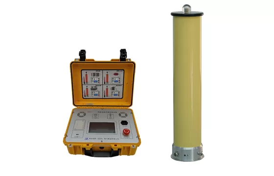
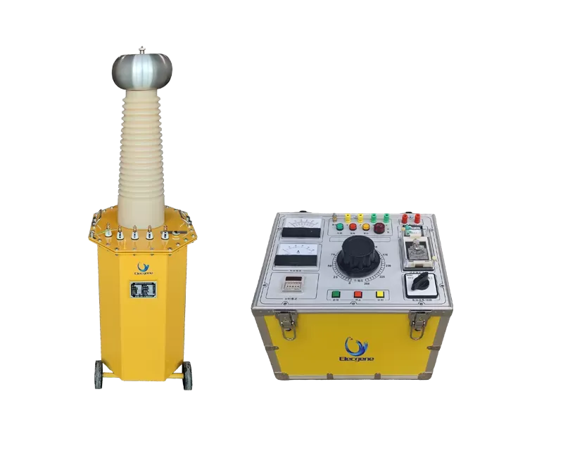
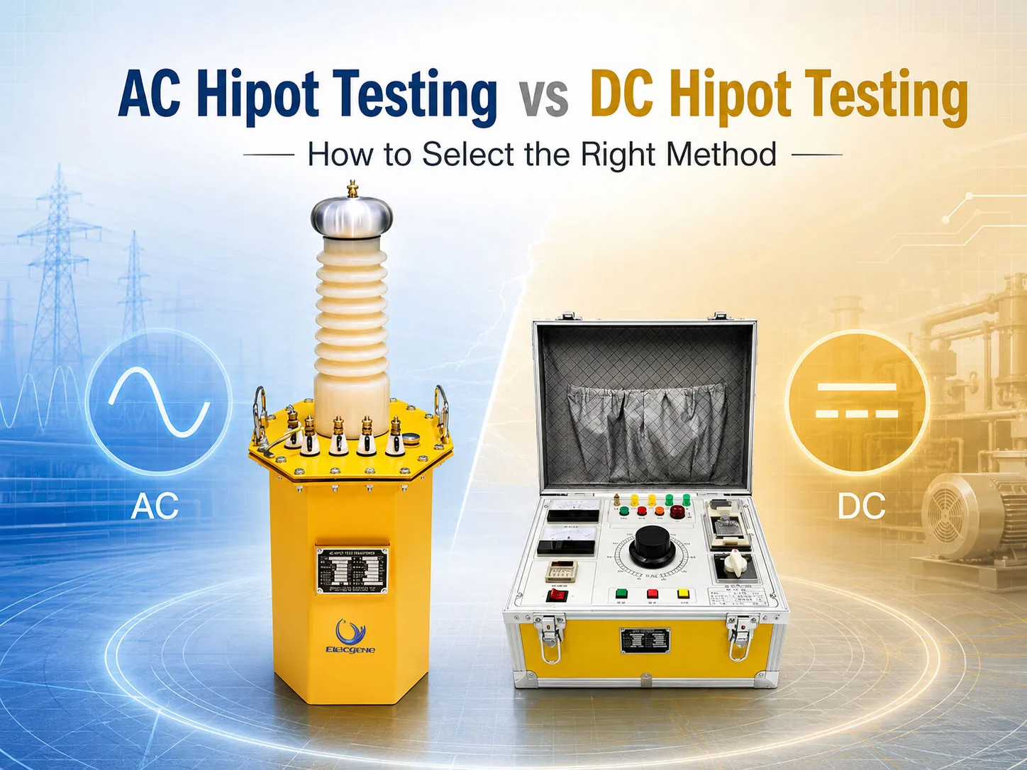
The Elecgene YTB-20 50 kV AC/70 kV DC high-voltage test system provides 50 kV AC output and can be fitted with an optional rectifier for 70 kV DC testing. Available 3, 5 and 10 kVA configurations provide up to 60, 100 and 200 mA AC respectively, with a listed duty cycle of five minutes on and fifteen minutes off.
This type of split control-unit and high-voltage-transformer arrangement is suitable where adjustable AC voltage, test timing and overcurrent protection are required.
Select DC Hipot Testing When
DC testing may be selected when:
The equipment standard or manufacturer explicitly specifies DC withstand testing
A surge arrester or other DC-oriented test procedure is involved
Leakage current must be monitored after charging and absorption currents decrease
The test object and insulation construction are suitable for DC stress
Portability is important
The required output current is within the DC test set’s capability
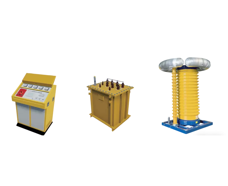
The Elecgene DHVT portable DC hipot tester is available with standard output voltages of 60, 120 and 200 kV and output-current configurations from 2 to 20 mA, depending on the selected model. Its listed ripple coefficient is no more than 0.5%, and the system is rated for intermittent operation at rated load for up to 30 minutes.
The DHVT series is intended for applications such as surge arresters and other equipment for which a DC withstand or leakage-current procedure has been approved. Product capability alone does not determine whether DC is technically appropriate for a specific transformer, generator, breaker or cable.
Review Leakage Current, Duty Cycle and Trip Settings
A hipot tester must supply the expected load current without nuisance tripping.
For AC equipment, check:
For DC equipment, check:
The protection-current setting must be high enough to allow normal charging current but low enough to respond appropriately to breakdown or excessive leakage.
Plan the High-Voltage Test Area and Discharge Procedure
High-voltage testing should only be performed by qualified personnel using an isolated test area, suitable grounding and an approved operating procedure.
For high-capacitance equipment, OSHA 29 CFR 1910.269(o) requires stored energy to be reduced safely before a direct ground is applied. It specifically calls for high-capacitance equipment to be discharged through a resistor rated for the available energy before exposed terminals are directly grounded.
The test workflow should include:
Isolating and identifying the test object
Establishing barriers and access control
Verifying the grounding arrangement
Confirming voltage, current and time settings
Raising the voltage at the approved rate
Monitoring current and protection status
Reducing the output to zero
Discharging stored energy
Applying a direct protective ground
Confirming absence of voltage before contact
Conclusion: Match the Hipot Method to the Insulation and Standard
The correct hipot test is the method that applies the required electrical stress without exceeding the limitations of the insulation, test source or approved procedure.
AC hipot testing is generally preferred when an alternating withstand voltage is specified or when the test should reproduce reversing-polarity stress. DC hipot testing is useful when an approved DC procedure requires portable high voltage or time-dependent leakage-current measurement.
The decision should not be based solely on equipment size, maximum voltage or the assumption that one waveform is more severe. The test engineer must consider:
The equipment and insulation type
The applicable standard
Required voltage and duration
Load capacitance
Output-current demand
Leakage-current interpretation
Duty cycle
Stored-energy risk
Required documentation
Elecgene offers portable DC instruments and split AC/DC high-voltage systems for different field and laboratory requirements. To obtain an appropriate recommendation, provide the equipment type, insulation system, rated voltage, specified test voltage, capacitance, test duration and applicable standard.
FAQ
1. Is AC hipot testing more severe than DC hipot testing?
Not universally. AC and DC create different electric-field and current behavior within an insulation system. The severity depends on the insulation materials, geometry, voltage level, waveform, duration and acceptance criteria. The test method specified by the applicable equipment standard should be used rather than assuming that AC or DC is always more severe.
2. Can I convert an AC hipot voltage to DC by multiplying by 1.414?
No. Multiplying RMS AC voltage by 1.414 calculates the peak of an ideal sinusoidal waveform, but it does not establish an equivalent DC withstand voltage.
AC and DC test levels must be taken from the applicable standard or manufacturer procedure because field distribution, duration and failure behavior can differ.
3. Is AC or DC hipot testing better for power cables?
It depends on the cable insulation and test objective. Laminated dielectric, extruded dielectric and other cable systems may require different methods.
The engineer should review the cable manufacturer’s instructions and the applicable cable-testing standard before selecting DC, power-frequency AC, resonant AC or VLF.
4. Why is an AC hipot tester often larger than a DC hipot tester?
A capacitive test object continuously draws charging current during an AC test. As capacitance, frequency or voltage increases, the required reactive capacity also increases.
During a DC test, the high initial charging current normally falls after the insulation is charged, leaving absorption and leakage components.
5. Can DC leakage current determine whether insulation is good or bad?
Leakage current can provide useful information, but it should not be interpreted from one number alone.
Results may be influenced by temperature, humidity, surface contamination, test duration, previous charging, insulation type and test voltage. Compare the result with the approved limit, historical data and other diagnostic tests.
6. How long should equipment remain grounded after a DC hipot test?
There is no universal grounding time for every test object. The required time depends on capacitance, voltage, insulation absorption, discharge resistance and the approved safety procedure. The equipment must remain discharged and grounded until stored energy has fallen to a safe level and absence of voltage has been verified.

 English
  日本語
日本語  한국어
한국어  français
  Deutsch
  русский
  português
  العربية