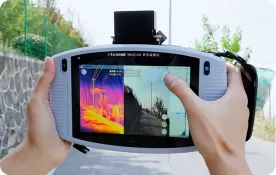
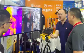
An acoustic imaging camera visualizes sound sources, while a thermal camera visualizes surface-temperature patterns. Although both technologies allow non-contact industrial inspection, they detect different physical signals and reveal different types of faults.
An acoustic camera is generally the better choice for locating compressed-air leaks, gas leaks, abnormal mechanical noise, corona, arcing and acoustic emissions associated with partial discharge. A thermal camera is better suited to identifying overheating, abnormal temperature differences, poor electrical connections, overloaded components and thermal insulation problems.
Neither technology is universally better. The correct choice depends on whether the suspected problem produces sound, heat or both.
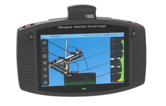
For maintenance teams that handle multiple fault types, combining acoustic and thermal imaging can provide stronger evidence than relying on either technology alone. Elecgene supports this approach through its acoustic imaging camera and integrated acoustic-thermal inspection solutions.
How Acoustic Imaging Cameras and Thermal Cameras Work
An acoustic imaging camera maps audible or ultrasonic sound sources, whereas a thermal camera maps infrared radiation emitted and reflected by an object’s surface.
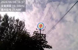
An acoustic imaging camera uses an array of microphones to collect sound arriving from different directions. Signal-processing and beamforming algorithms calculate where the sound originates and overlay the result as a colored acoustic map on a visible image.
Because many leaks and electrical defects produce high-frequency sound, an acoustic camera can locate signals that are difficult or impossible for the human ear to distinguish in a noisy industrial environment.
Typical acoustic imaging targets include:
Compressed-air and pressurized-gas leaks
Vacuum leaks
Valve and pipe leakage
Corona discharge
Electrical arcing
Surface discharge
Partial discharge acoustic emissions
Bearing and mechanical noise
Acoustic methods are recognized as one approach to locating partial discharge activity. IEC TS 62478:2016 covers electromagnetic and acoustic measurements of partial discharges in electrical insulation and includes considerations for PD location and sensitivity verification.
A thermal camera works differently. It detects infrared radiation from a target surface and converts the detected energy into a temperature-distribution image, commonly called a thermogram.
Thermal imaging can reveal:
Overheated breaker or switch contacts
Loose electrical connections
Phase-to-phase temperature imbalance
Overloaded cables
Motor or bearing overheating
Blocked cooling systems
Steam-trap problems
Heat loss through insulation
Abnormal friction
Thermal measurement is affected by emissivity, reflected apparent temperature, distance, atmosphere and viewing angle. ISO 18434-1:2008 provides procedures for using infrared thermography in machinery condition monitoring, including guidance on emissivity, reflected temperature, data interpretation and reporting. The standard was reviewed and confirmed in 2023 and remains current.
In practical terms, an acoustic camera answers:
Where is the sound-producing fault?
A thermal camera answers:
Where is the abnormal surface-temperature pattern?
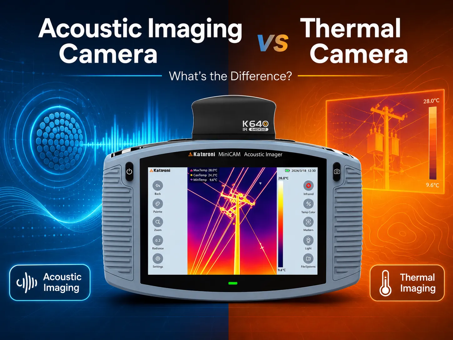
Acoustic Imaging Camera vs Thermal Camera: Key Differences
The main difference between acoustic and thermal imaging is the signal being measured: acoustic imaging measures sound pressure, while thermal imaging evaluates infrared surface-temperature patterns.
| Comparison | Acoustic Imaging Camera | Thermal Camera |
|---|
| Primary Signal | Audible and ultrasonic sound | Infrared radiation |
| Main Output | Sound-source location map | Surface-temperature image |
| Typical Measurements | Sound level, frequency and source position | Temperature, temperature difference and thermal pattern |
| Best Applications | Gas leaks, compressed-air leaks, partial discharge, arcing and mechanical noise | Overheating, loose electrical joints, friction and thermal insulation defects |
| Humanly Detectable Signal Required | No; ultrasonic signals may be detected | No; infrared radiation is outside visible light |
| Main Environmental Influences | Background noise, reflections, distance and frequency filtering | Emissivity, reflected temperature, wind, load and viewing angle |
| Can Locate Compressed-Air Leaks? | Yes | Normally no |
| Can Identify Overheating? | Not by sound alone | Yes |
| Can Support Energized Inspection? | Yes, when site safety requirements are followed | Yes, when site safety requirements are followed |
| Main Limitation | A defect must generate detectable sound | A defect must create a detectable surface-temperature difference |
Acoustic Cameras Locate Energy Loss That Thermal Cameras May Miss
A compressed-air leak may produce a strong ultrasonic signal without creating a meaningful temperature difference. An acoustic camera can survey a large installation and show the direction and position of the leak on the screen.
This matters because compressed-air leakage can represent a substantial operating cost. The U.S. Department of Energy reports that leaks can waste 20%–30% of a compressor’s output. Its technical guidance also identifies ultrasonic acoustic detectors as an effective method for recognizing the high-frequency hissing associated with air leaks. Read the DOE compressed-air leak guidance.
Thermal Cameras Quantify Surface-Temperature Anomalies
A thermal camera is more useful when the fault changes the surface temperature of the equipment.
For example, a poor busbar connection can produce resistive heating. The thermal image may show that one phase or connection is hotter than comparable components under similar load conditions.
However, the displayed temperature is not automatically the internal temperature of the equipment. Surface material, emissivity, reflections and operating load must be considered before a maintenance decision is made.
Both Technologies Are Non-Contact, but Neither Eliminates Verification
Acoustic and thermal cameras allow inspectors to evaluate operating equipment from a distance. This can reduce unnecessary contact with machinery and high-voltage components, but it does not remove electrical or industrial safety requirements.
An acoustic hotspot should still be verified using the appropriate leak, electrical or mechanical test. A thermal anomaly should be assessed against equipment load, ambient conditions, comparable phases and historical measurements.
Which Inspection Camera Should You Use?
Camera selection should be based on the fault’s physical symptom, the operating environment and the maintenance decision that must be made.
Choose an Acoustic Imaging Camera for Leaks and Sound-Producing Faults
An acoustic imaging camera is normally the better option when technicians need to locate:
Industrial leak detection is especially suitable for acoustic imaging because many possible leak points can be scanned rapidly without applying soapy water to each individual fitting.
For electrical systems, acoustic imaging is useful as an online localization tool. In Elecgene’s 10kV overhead-line partial discharge case, an acoustic image was used to localize discharge activity around an overhead-line insulator while the line was inspected from a safe working position.
Acoustic imaging does not necessarily quantify partial discharge in apparent charge. Where required, the result should be combined with an appropriate electrical PD measurement, insulation test or equipment-specific diagnostic procedure.
Choose a Thermal Camera for Temperature-Related Faults
A thermal camera is normally more suitable for:
Overheated switchgear connections
Circuit breaker contact heating
Cable termination hotspots
Transformer cooling problems
Motor temperature imbalance
Bearing friction
Mechanical overheating
Insulation heat loss
The equipment should usually be inspected under representative operating conditions. A loose electrical connection may not produce a meaningful thermal anomaly when the circuit carries little or no load.
Inspectors should also compare similar components rather than judging one temperature in isolation. Three phases, parallel conductors or identical bearings can provide useful comparison references.
Use Both When a Fault Can Produce Sound and Heat
Some failures produce both acoustic and thermal symptoms.
Electrical arcing may create ultrasound before it produces an obvious thermal hotspot. A deteriorating bearing may generate abnormal sound before friction causes a large temperature increase. A leaking gas valve may produce ultrasound while process conditions also create a temperature difference.
Using both technologies can therefore help answer two separate questions:
Is there a sound-producing defect, and where is it?
Has the defect also created a measurable temperature anomaly?
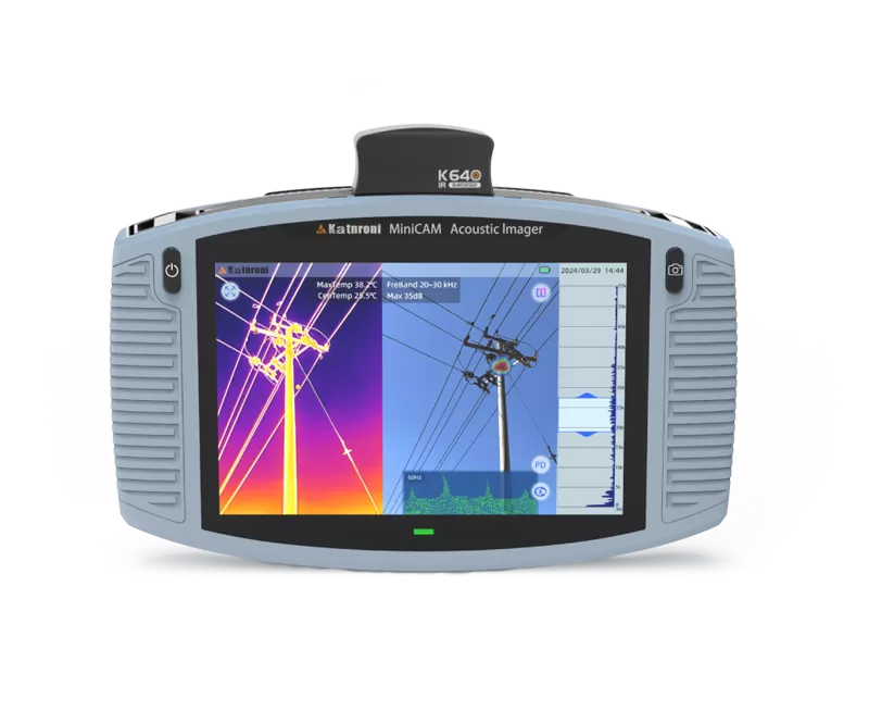
The Elecgene MiniCAM acoustic imager with an optional thermal module is designed for this combined workflow. Its acoustic system uses 128 digital microphones, covers a stated effective frequency range of 2–55 kHz and weighs approximately 1.25 kg. The optional thermal module provides 640 × 512 infrared resolution, a stated temperature range of −20°C to 650°C and accuracy of ±2°C or ±2%, subject to the measurement conditions.
The following selection guide summarizes the recommended starting point:
| Inspection Objective | Recommended Technology |
|---|
| Find compressed-air or gas leaks | Acoustic imaging |
| Locate corona, arcing or acoustic PD | Acoustic imaging |
| Find an overheated electrical connection | Thermal imaging |
| Compare phase temperatures | Thermal imaging |
| Investigate abnormal mechanical noise | Acoustic imaging |
| Assess bearing overheating | Thermal imaging |
| Find an early fault with uncertain symptoms | Combined acoustic and thermal imaging |
| Inspect a potentially explosive area | Appropriately certified inspection equipment |
When selecting equipment, also evaluate detection range, frequency coverage, microphone count, infrared resolution, thermal sensitivity, temperature accuracy, battery runtime, environmental rating and hazardous-area certification.
Conclusion: Choose the Signal That Matches the Fault
The correct inspection camera is the one that measures the physical signal most closely related to the suspected defect.
Choose an acoustic imaging camera when the priority is locating leaks, discharge activity or abnormal noise. Choose a thermal camera when the priority is measuring surface-temperature differences and identifying overheated components.
For utilities, substations and industrial plants with mixed inspection needs, a combined workflow is often more effective. Acoustic imaging can locate an early sound-producing problem, while thermal imaging can show whether the same component has developed a temperature anomaly.
Elecgene recommends defining the test objects, inspection distance, operating environment and fault types before selecting a camera. This avoids paying for features that are not required while ensuring the chosen system can support the actual maintenance workflow.
Frequently Asked Questions
1. Can an acoustic imaging camera measure temperature?
A standard acoustic imaging camera does not measure temperature. It maps sound sources using a microphone array. Temperature measurement requires a separate thermal detector or an integrated thermal imaging module.
2. Can a thermal camera detect compressed-air leaks?
A standard thermal camera generally cannot reliably locate a compressed-air leak unless the leak creates a detectable surface-temperature difference. Acoustic imaging is usually more suitable because escaping pressurized gas produces high-frequency sound. Specialized optical gas-imaging cameras are a separate technology and should not be confused with standard industrial thermal cameras.
3. Which camera is better for partial discharge inspection?
An acoustic imaging camera is more suitable for locating partial discharge that produces detectable acoustic or ultrasonic emissions. Thermal imaging may identify heating caused by an advanced electrical fault, but early partial discharge may not generate an obvious surface-temperature change. Acoustic localization should be combined with other PD or insulation tests when quantitative diagnosis is required.
4. Which camera is better for inspecting electrical panels?
The answer depends on the fault. Thermal imaging is normally preferred for overheated terminals, phase imbalance and overloaded components. Acoustic imaging is useful for corona, arcing and discharge-related sound. Using both provides broader coverage.
5. Can acoustic and thermal cameras inspect energized equipment?
Both technologies can support non-contact inspection of energized equipment. Inspectors must still follow the required approach distances, personal protective equipment rules, arc-flash controls and site safety procedures. The camera’s stated detection range does not permit an operator to ignore electrical safety boundaries.
6. What information should I provide when selecting an inspection camera?
Provide the equipment being inspected, expected fault types, minimum and maximum working distance, background-noise conditions, required thermal range, hazardous-area classification, operating temperature, reporting requirements and expected inspection frequency. This information allows Elecgene to determine whether an acoustic, thermal or integrated inspection solution is more appropriate.

 English
  日本語
日本語  한국어
한국어  français
  Deutsch
  русский
  português
  العربية