Choosing an acoustic imaging camera requires more than comparing microphone count or maximum detection distance. The right camera must match the sound source, working distance, background noise, inspection environment and reporting requirements of the actual application. Acoustic imaging cameras use a microphone array and beamforming software to locate audible or ultrasonic sound and display the source as a visual map. They are commonly used for compressed-air and gas leak detection, partial discharge inspection, mechanical-noise localization and online electrical maintenance. A suitable camera should make faults easier to locate without creating excessive false indications or forcing technicians to spend additional time filtering unusable data. Elecgene recommends evaluating the complete inspection workflow before selecting from its acoustic imaging camera range.
What Specifications Matter When Choosing an Acoustic Imaging Camera?
The most important acoustic imaging camera specifications are microphone count, effective frequency range, detection distance, signal-to-noise performance, display quality, battery runtime and data-export capability. These parameters work together. One impressive specification does not compensate for weaknesses elsewhere.
Microphone Count and Array Design
An acoustic camera uses differences in the arrival time and phase of sound across multiple microphones to estimate the source position.
A larger microphone array can support:
Improved directional resolution
Better separation of nearby sound sources
More stable beamforming
Stronger performance at longer distances
Better visualization in complex environments
However, microphone count alone does not determine image quality. Array diameter, microphone spacing, calibration, processing algorithms and operating frequency are also important.
Two cameras with the same number of microphones may produce different results if one has better array geometry or noise-processing software.
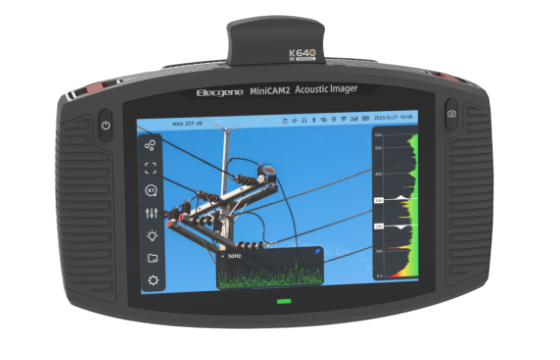
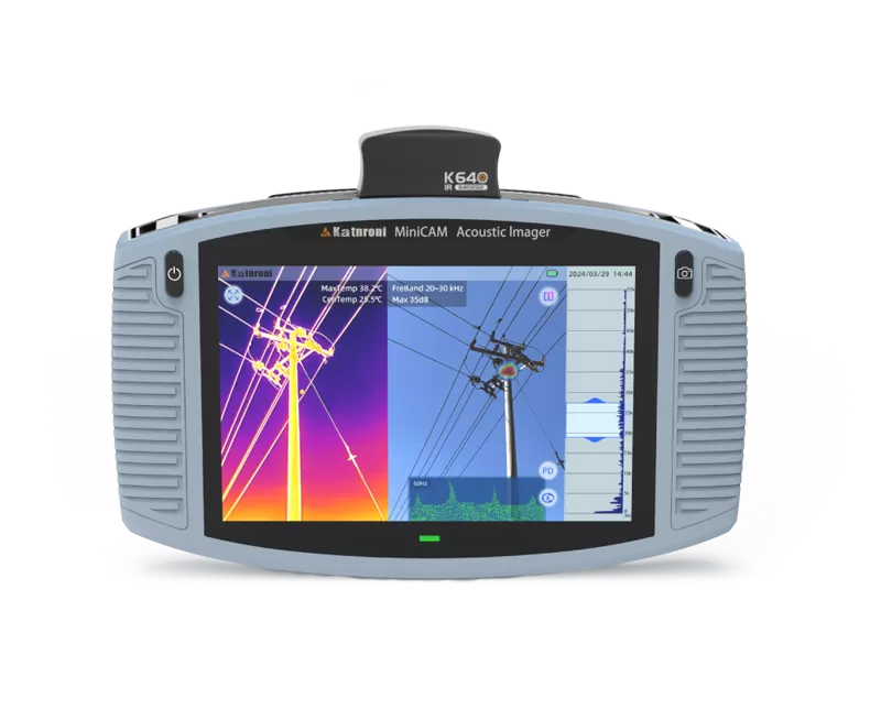
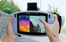
The Elecgene MiniCAM uses 128 digital microphones. Its stated signal-to-noise ratio is 64.3 dB(A), and the instrument displays acoustic results on a 7-inch, 1280 × 800-pixel screen.
Effective Frequency Range
Frequency range determines which sound components the camera can process.
Lower-frequency coverage can be useful for:
Mechanical vibration
Bearing noise
Valve operation
Audible air leakage
General industrial noise
Higher-frequency and ultrasonic coverage is particularly important for:
Many industrial leak sounds contain high-frequency energy that is easier to distinguish from ordinary plant noise. The U.S. Department of Energy recommends ultrasonic acoustic detection for compressed-air leakage because it can recognize the high-frequency hissing associated with escaping air. Its guidance also notes that leaks can waste 20%–30% of compressor output in poorly maintained systems. See the targeted DOE compressed-air leak guidance.
The MiniCAM has a stated effective frequency range of 2–55 kHz, with extended configurations available. That range supports both audible industrial noise and ultrasonic leak or electrical-fault applications.
Detection Distance
Maximum distance figures should be treated as application-dependent rather than guaranteed performance.
Actual detection distance depends on:
Elecgene lists a detection range of approximately 0.3–200 m for the standard MiniCAM, subject to actual test conditions. The hazardous-area MiniCAM-ATEX is described as detecting selected leaks and electrical faults from distances of up to 120 m.
A camera that can detect a strong source at 200 m will not necessarily detect a very small compressed-air leak at the same distance. Buyers should request a demonstration using a representative target whenever long-range detection is critical.
Display, Storage and Battery Runtime
Acoustic inspections often take place in substations, production facilities and outdoor areas. The camera must therefore be practical to operate while the technician is moving.
Useful operational specifications include:
| Specification | Why It Matters |
|---|
| Screen size and brightness | Supports outdoor viewing and accurate hotspot selection |
| Image frame rate | Affects the smoothness of real-time localization |
| Internal storage | Determines how many images and videos can be retained |
| Image and video formats | Affect reporting and evidence sharing |
| USB export | Simplifies transfer to computers and maintenance systems |
| Battery runtime | Determines whether a full inspection route can be completed |
| Instrument weight | Affects fatigue during extended handheld use |
| Operating temperature | Determines suitability for outdoor and industrial environments |
The MiniCAM provides 30 FPS imaging, 64 GB storage expandable to 128 GB, JPG and MP4 recording, USB Type-C data export and a stated battery runtime of approximately five hours. Its weight is approximately 1.25 kg, and its stated operating range is −20°C to 50°C.
Which Acoustic Imaging Camera Fits Your Inspection Application?
An acoustic imaging camera should be selected according to the fault type because gas leaks, electrical discharge and mechanical noise produce different frequency patterns and require different inspection workflows.
Compressed-Air and Industrial Gas Leak Detection
For compressed-air inspection, prioritize:
Ultrasonic frequency coverage
Fast scanning across large areas
Clear visual hotspot display
Frequency filtering
Image and video recording
Leak documentation
Lightweight field operation
Compressed-air leaks commonly occur at couplings, hoses, fittings, pipe joints, quick disconnects, regulators, valves, flanges and point-of-use equipment. The DOE also notes that leakage increases with system pressure and that flow can rise substantially as the leak opening becomes larger.
A useful camera should allow the technician to scan from a distance, identify the likely direction of the leak and then move closer for confirmation.
The camera does not replace repair verification. After the fitting, hose or valve is repaired, the area should be scanned again to confirm that the acoustic source has been removed.
Partial Discharge and Electrical Fault Detection
For electrical inspection, prioritize:
Strong ultrasonic performance
Long working distance
Stable localization around complex equipment
Frequency selection
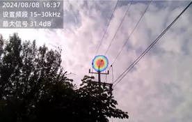
Corona and arcing visualization
Image and video evidence
Safe non-contact operation
Acoustic imaging can help locate:
Corona around insulators
Surface discharge
Electrical arcing
Discharge around switchgear
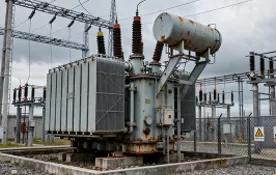
Abnormal sound from transformers
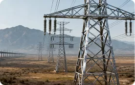
Overhead-line insulation faults
IEC TS 62478:2016 applies to electromagnetic and acoustic measurements of partial discharge in electrical apparatus. It addresses applications involving sensors with different frequency ranges and sensitivities, as well as PD location and sensitivity checks.
Acoustic imaging is primarily a localization and screening method. It does not automatically replace charge-based partial discharge measurement, insulation testing or equipment-specific diagnostic procedures. A bright acoustic hotspot indicates where sound energy is concentrated, but it does not by itself state the exact internal defect or apparent charge level.
Mechanical and Abnormal-Noise Inspection
For machinery inspection, useful functions include:
Audible and ultrasonic frequency coverage
Narrow-band filtering
Recording of video and sound
Comparison between similar assets
Stable localization around rotating equipment
Applications may include:
Bearing noise
Valve chatter
Steam-trap leakage
Abnormal friction
Loose mechanical components
Pneumatic actuator leakage
Unusual transformer or reactor sound
Maintenance teams should compare similar machines under comparable speed and load. A strong acoustic source is not necessarily a fault if it is normal for that equipment design.
How Should Microphone, Software, Thermal and ATEX Options Be Compared?
A complete acoustic imaging camera evaluation should compare both sensing hardware and workflow features, including filtering, thermal integration, hazardous-area certification and report generation.
Camera Comparison Table
| Selection Factor | Entry-Level Industrial Camera | Advanced Acoustic Camera | Acoustic-Thermal Camera | ATEX Acoustic Camera |
|---|
| Main Application | Basic leak localization | Leaks, PD and mechanical faults | Acoustic plus temperature-related faults | Inspection in classified hazardous areas |
| Microphone Array | Smaller or basic array | Higher-count calibrated array | Advanced array plus infrared sensor | Certified array and enclosure |
| Frequency Filtering | Basic presets | Adjustable bands and advanced filtering | Acoustic filtering plus thermal settings | Filtering suitable for classified-site workflow |
| Thermal Measurement | No | Optional on some models | Integrated or removable thermal module | Model-dependent |
| Reporting | Images or basic export | Images, video and detailed records | Acoustic and thermal evidence | Certified-site inspection records |
| Best User | Small maintenance team | Utilities and industrial inspection teams | Mixed electrical and mechanical inspection | Petrochemical and process facilities |
| Main Buying Risk | Limited range or filtering | Paying for unnecessary advanced functions | Assuming thermal imaging replaces acoustic analysis | Using non-certified equipment in a hazardous area |
Frequency Filtering and Background-Noise Control
Factories and substations can contain:
Motors
Fans
Pneumatic tools
Transformers
Vehicles
Wind
Speech
Reflected sound
A good acoustic camera should allow technicians to focus on the frequency range associated with the suspected fault.
For example, narrowing the displayed band may help separate a high-frequency air leak from lower-frequency machinery noise. Frequency filtering does not remove all interference, but it can improve source visibility and reduce false hotspots.
The user should also be able to adjust:
Acoustic and Thermal Imaging Integration
Acoustic and thermal imaging detect different physical signals.
Acoustic imaging locates sound-producing faults such as:
Thermal imaging identifies surface-temperature patterns such as:
For teams that regularly inspect both electrical and mechanical assets, an integrated system can reduce the need to carry two separate devices.
The Elecgene MiniCAM with optional thermal module combines the 128-microphone acoustic camera with a 640 × 512-pixel infrared module. The thermal module has a stated NETD of 25 mK at 30°C, a temperature range of −20°C to 650°C, and stated accuracy of ±2°C or ±2% under specified conditions.
Thermal capability should be selected only when it supports the inspection workflow. A thermal module does not improve acoustic leak localization, and acoustic imaging does not measure temperature.
ATEX Certification for Hazardous Areas
Standard industrial electronics should not be taken into a potentially explosive atmosphere unless the equipment has the appropriate certification for the classified area.
The European Commission explains that an explosive atmosphere can form when air mixes with gases, vapours, mists or dusts under conditions that allow ignition. The ATEX Directive 2014/34/EU covers equipment and protective systems intended for use in these environments and establishes essential safety requirements and conformity-assessment procedures.
The Elecgene MiniCAM-ATEX carries the stated marking II 3G Ex ic IIC T5 Gc and is intended for relevant Zone 2 applications. It supports gas, pressure and vacuum leak detection, as well as corona, arcing and acoustic partial discharge inspection.
The camera marking must still be checked against:
An ATEX label alone does not mean the equipment is suitable for every hazardous area.
Software, Reports and Data Management
The camera should produce evidence that maintenance teams can act on.
A useful report should include:
Asset identification
Inspection date and location
Acoustic image
Visible image
Selected frequency band
Approximate working distance
Sound-level information
Technician notes
Fault priority
Recommended corrective action
Post-repair verification
For compressed-air programs, the ability to track leaks by asset and repair status may be more valuable than a small improvement in microphone count.
For electrical inspections, images should clearly show the acoustic source in relation to the insulator, conductor, bushing or switchgear component.
Conclusion: Select the Camera Around the Inspection Workflow
The best acoustic imaging camera is the one that consistently locates the required faults under real site conditions and produces evidence that technicians can use for maintenance decisions.
Do not select a camera only because it has the most microphones, the longest advertised distance or the widest frequency range.
A practical selection process should evaluate:
The main fault types
Required frequency coverage
Expected inspection distance
Background-noise conditions
Indoor or outdoor operation
Image, video and reporting needs
Battery and portability requirements
Thermal-imaging requirements
Hazardous-area classification
Available training and technical support
Elecgene offers standard, thermal-enabled and ATEX-certified acoustic imaging configurations. To receive an appropriate recommendation, provide the inspection objects, expected fault types, minimum and maximum distance, background-noise conditions, hazardous-area requirements and annual inspection volume.
FAQ
1. Does a higher microphone count always mean better acoustic imaging?
No. More microphones can improve localization and resolution, but performance also depends on array size, microphone spacing, calibration, beamforming algorithms, frequency range and noise processing. Compare real inspection results rather than microphone count alone.
2. What frequency range is best for compressed-air leak detection?
Compressed-air leaks often generate useful ultrasonic energy above the normal audible range. A camera covering frequencies into the tens of kilohertz is generally suitable.
The best band depends on leak pressure, opening size, background noise and working distance. Adjustable filtering is more useful than one fixed ultrasonic setting.
3. How far away can an acoustic imaging camera detect a leak?
Detection distance varies with source strength and environmental conditions. A large high-pressure leak may be detected from much farther away than a small low-pressure leak. Wind, noise, reflections and obstacles can also reduce useful range. Treat the manufacturer’s maximum distance as a reference, not a guarantee for every fault.
4. Can one acoustic camera detect both gas leaks and partial discharge?
Yes, provided the camera has suitable frequency coverage, filtering and sensitivity. However, gas leak detection and electrical partial discharge require different inspection procedures and result interpretation. Acoustic PD localization may also need confirmation using electrical or insulation diagnostic equipment.
5. Should I choose an acoustic camera with a thermal module?
Choose a thermal module when the maintenance team also needs to identify overheating, phase-temperature imbalance, bearing friction or other surface-temperature anomalies.
A thermal module is less important when the camera will be used almost exclusively for compressed-air leakage.
6. When is an ATEX acoustic imaging camera required?
An appropriately certified camera is required when inspection takes place inside a classified potentially explosive atmosphere and the site assessment specifies such equipment.
The exact camera marking must match the site’s zone, gas or dust group, temperature class and equipment protection requirements.

 English
  日本語
日本語  한국어
한국어  français
  Deutsch
  русский
  português
  العربية