PART 1: Main Information of On-site Test
Table 1: Test Details & Basic Information
| Category | Details |
| Test Time | 2025.4.9 |
| On-site Tester | Li Deyao |
| Weather | Sunny |
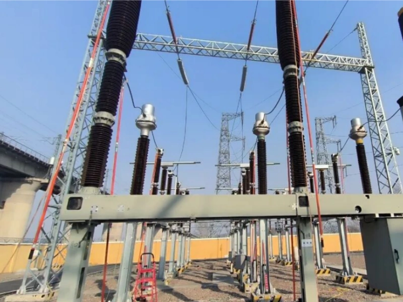
| Test Location | A 110kV Traction Substation |
| Test Object Type | Current Transformer |
| Voltage Level | 110kV |
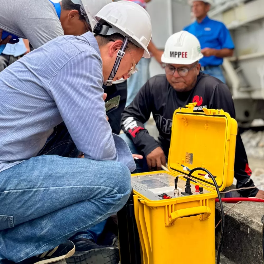
| Test Items | Transformer dielectric loss, turns ratio, polarity, excitation test, and primary current injection |
| Instruments Used | DLT-800, TCT-200F, PRE 3000 |
| Test Data | Yes |
PART 2: Overview
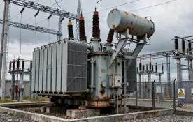
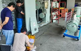
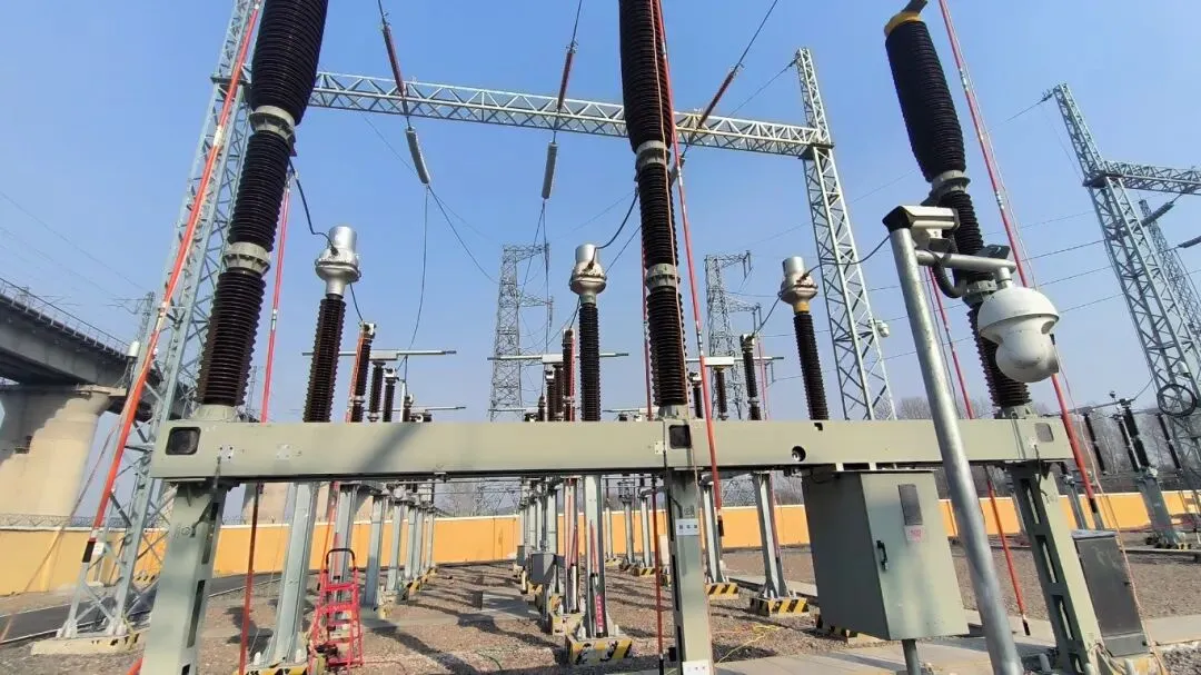
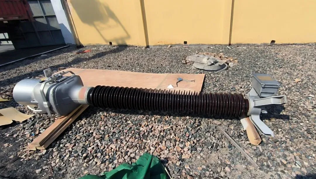
A 110kV current transformer in a traction substation had abnormal noise during operation, posing a significant hidden danger. To prevent a failure during operation that could lead to a power outage, this current transformer was replaced. This testing work mainly conducts dielectric loss tests, turns ratio, polarity, excitation characteristics, and secondary winding DC resistance tests on the new current transformer, as well as a primary current injection test after installation.
PART 3: Reference Standards
This test will be conducted on the new current transformer with reference to GB 50150-2016 "Standard for hand-over test of electrical equipment".
PART 4: Test Purpose
To inspect whether the quality of the electrical equipment produced by the manufacturing unit is qualified;
To inspect whether the electrical equipment has been damaged during the installation and construction process, and whether the installation quality meets the regulatory requirements;
To inspect whether the newly installed electrical equipment meets the technical condition requirements for being put into power system operation.
PART 5: Test Items and Equipment Used
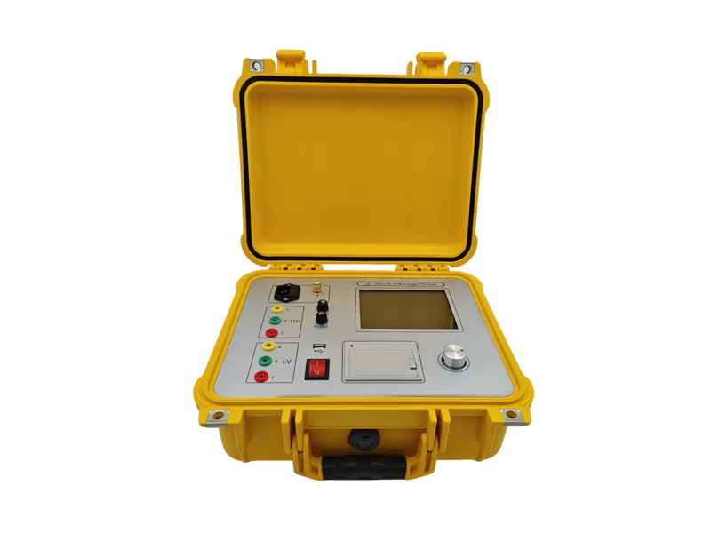
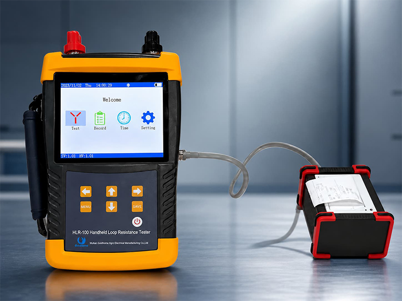
1) Current transformer turns ratio, polarity, excitation characteristics, and secondary winding DC resistance test
| Test Item | Test Instrument | Instrument Picture |
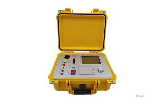
| Turns Ratio & Polarity Test | HXOT 472D Transformer Comprehensive Characteristics Tester | (Picture of HXOT 472D)
|
| Excitation Characteristics Test | ^ | ^ |
| Secondary Winding DC Resistance Test | ^ | ^ |
| Ratio Error and Phase Error Test | ^ | ^ |
| Transformer Dielectric Loss Test | DLT-800 Intelligent Anti-interference Dielectric Loss Tester | (Picture of DLT-800)
|
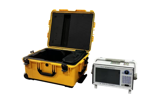
| Primary Current Injection Test | PER 3000 Relay Protection Phasor Inspection Complete Device | (Picture of PER/PRE 3000)
|
PART 6: I. Current Transformer Information
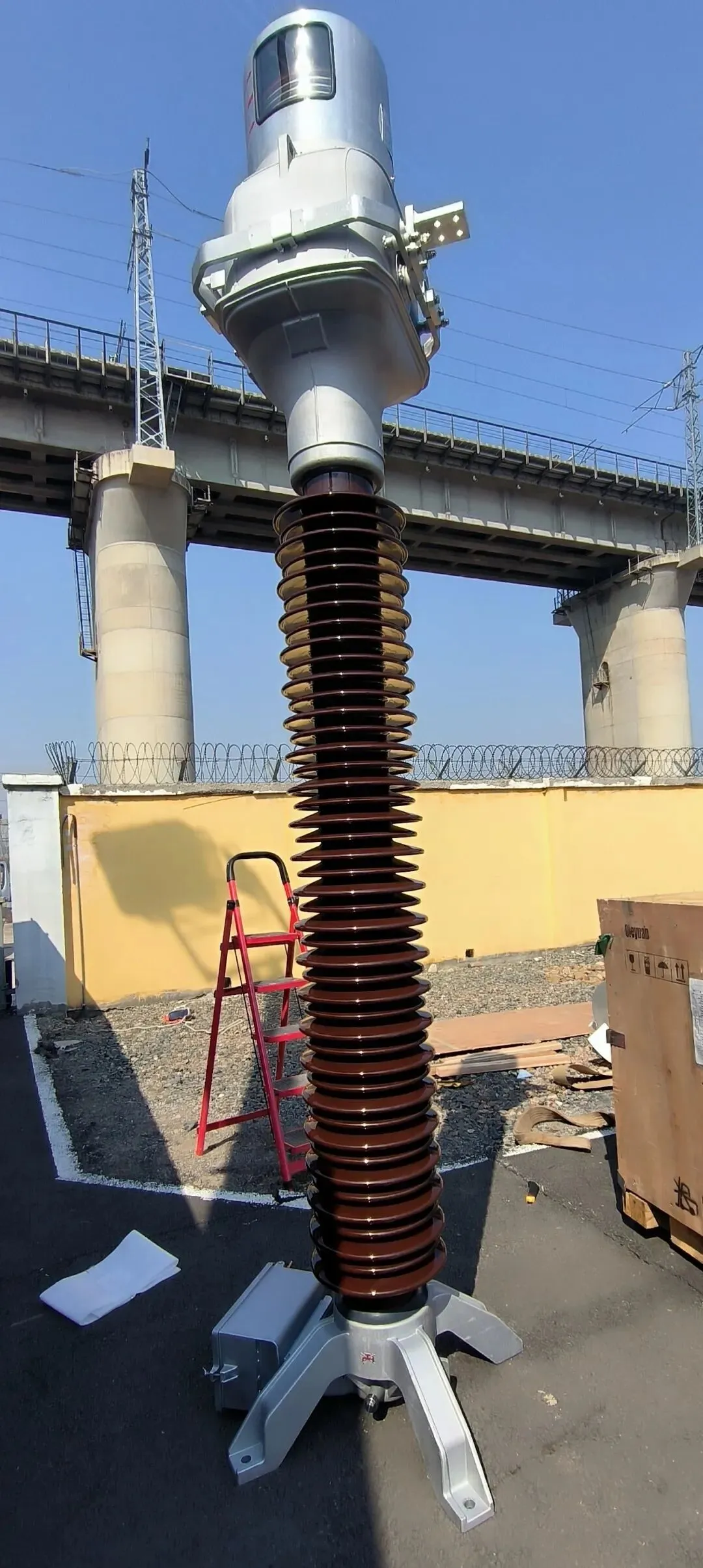
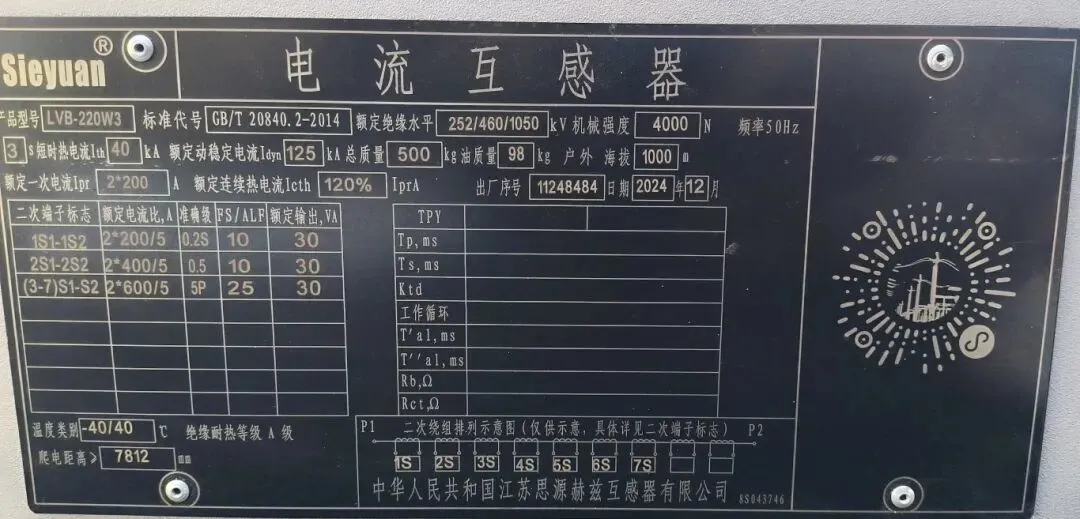
The rated voltage level of the tested transformer is 110kV, and it has seven sets of secondary windings. The specific information is shown below:
PART 7: II. Transformer Comprehensive Characteristics Test
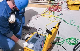
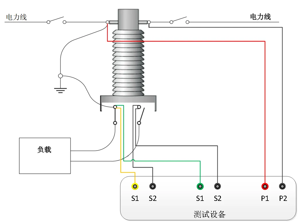
2.1 Perform turns ratio, polarity, excitation characteristics, winding DC resistance, and ratio/phase error tests on the current transformer. By wiring according to the schematic diagram below, all items can be completed at once without the need to change the wiring midway. Test the secondary windings one by one and record the test results.
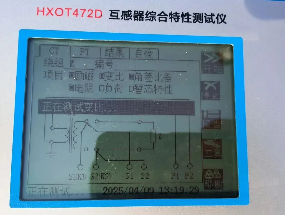
2.2 Comparing the test results with the factory report, the turns ratio error is within the qualified range, the polarity result is the same polarity, and the knee-point voltage of the protection winding excitation test is not lower than the factory value.
PART 8: III. Current Transformer Dielectric Loss Test
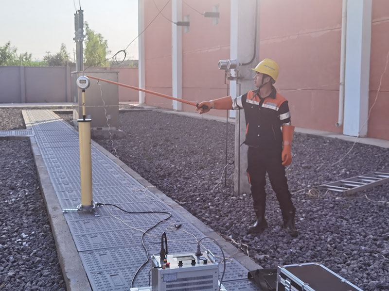
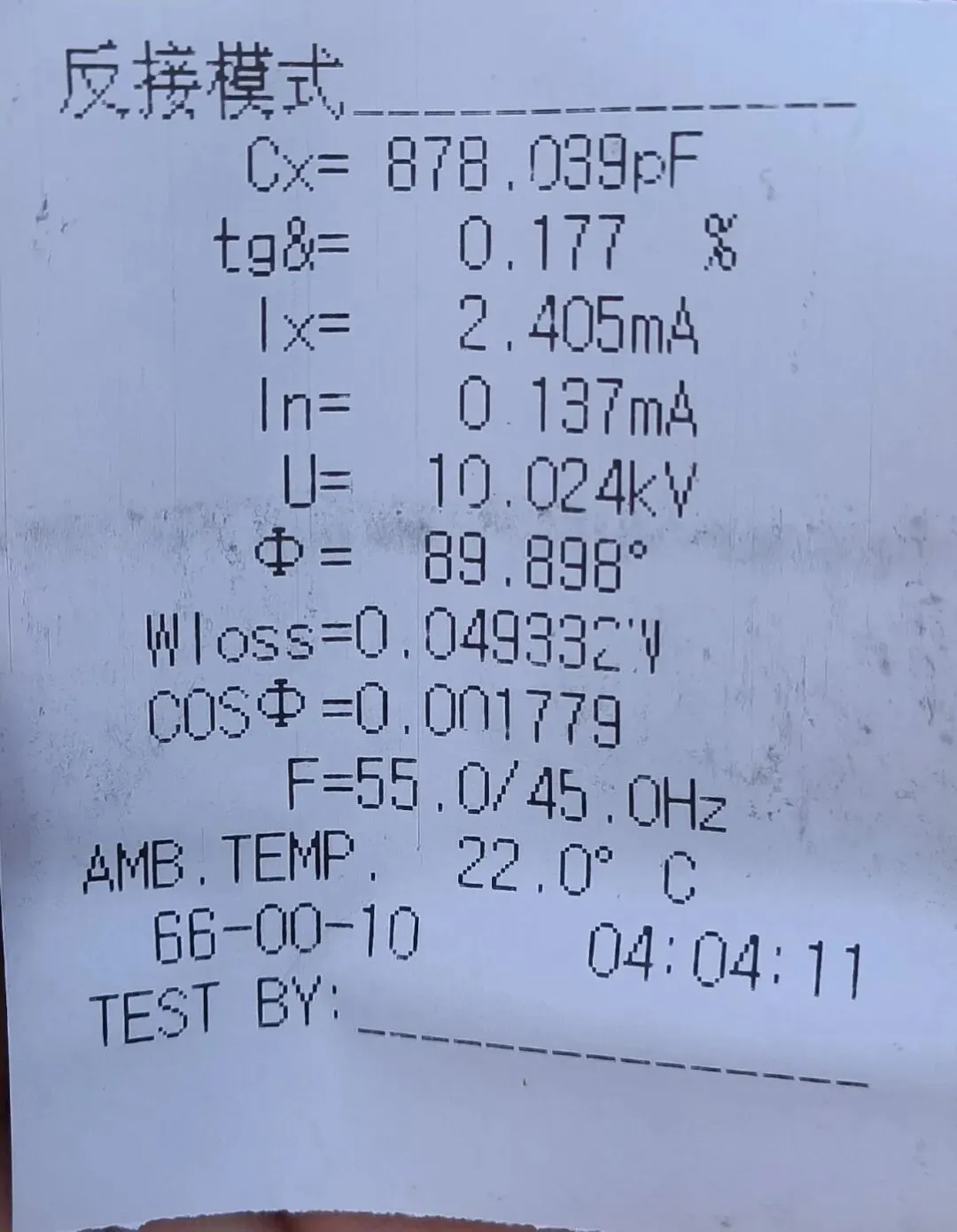
3.1 Short-circuit the primary side of the transformer, short-circuit the secondary side and ground it together with the terminal screen and the outer shell. Use the reverse connection method to test the dielectric loss factor of the primary side to the entire body.
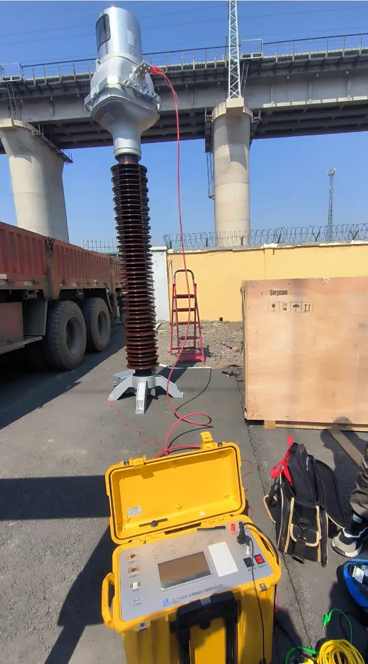
3.2 Compare the test results with the factory values. According to the handover test standard requirements, the dielectric loss factor of the 110kV oil-immersed current transformer should be ≤0.8%, and the capacitance value should not exceed 5% compared to the factory test. The factory value for the dielectric loss factor is 0.192%, and the tested value is 0.177%. The factory test value for the capacitance is 908.6pF, and the tested value is 878.039pF. The capacitance deviation is 3.3%, which meets the standard requirements.
PART 9: IV. Current Transformer Primary Current Injection Test
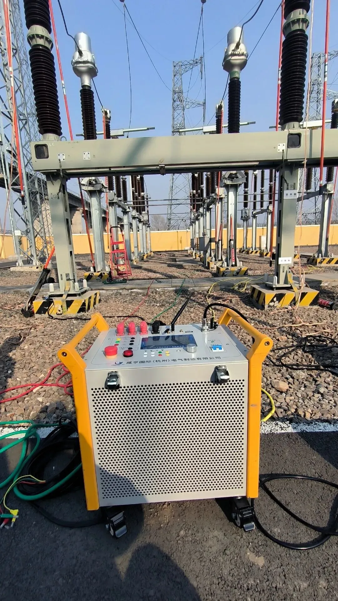
The purpose of the primary current injection test is to check for problems that may occur during the installation of the transformer, such as current loop wiring errors, open circuits, and short circuits. Before putting it into operation and starting it up, it is necessary to conduct a primary current and voltage injection test to simulate the load operation of the substation. This checks the correctness of the primary equipment phases, the correctness of the transformer turns ratio and polarity, and the integrity of the transformer's secondary loop.
A current of 30A is loaded onto the primary side to generate a small detectable current on the secondary side. By viewing the current amplitude and phase relationship, one can check whether the transformer installation wiring is correct.

 English
  日本語
日本語  한국어
한국어  français
  Deutsch
  русский
  português
  العربية