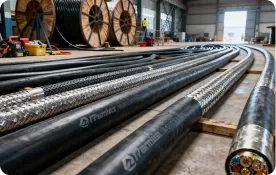
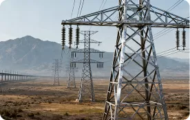
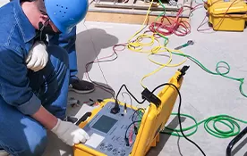
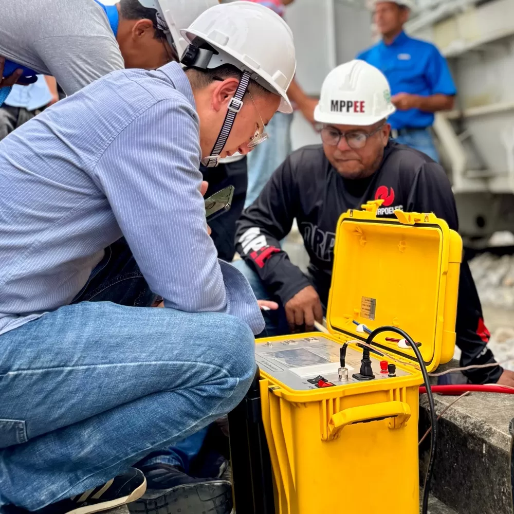
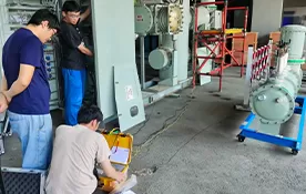
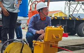
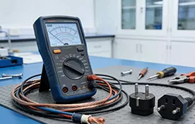
High contact resistance in circuit breakers and busbar joints is usually caused by poor metal-to-metal contact, surface contamination, oxidation, loose mechanical pressure, contact wear, misalignment or thermal damage. In high-current power systems, even a small increase in micro-ohm resistance can create abnormal heating because power loss rises with I²R, meaning heat increases with the square of current.
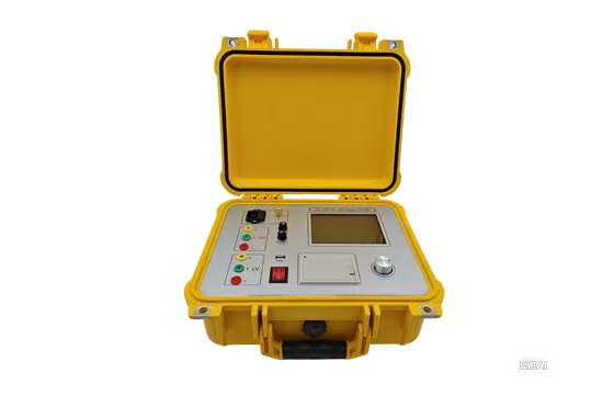
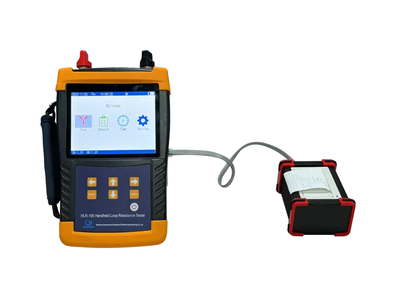
For substations, switchgear rooms, industrial plants and utility maintenance teams, contact resistance testing is a critical condition-assessment method. Elecgene supports this work with the HLR-100 Handheld 100A Micro-Ohmmeter, HLR-200 Handheld 200A Micro-ohmmeter and HVS-50 Circuit Breaker Analyzer for circuit breaker contacts, busbar joints, disconnectors and high-current connections.
What Is Contact Resistance in Power Equipment?
Contact resistance is the electrical resistance created at the interface between two conductive surfaces, such as breaker contacts, bolted busbar joints, disconnecting switches, cable lugs or grounding connections. It is normally very low, often measured in micro-ohms, but it becomes dangerous when the contact area is reduced or contaminated.
In high-voltage switchgear, resistance measurement is part of equipment verification and maintenance. IEC 62271-1 applies to AC switchgear and controlgear above 1,000 V, while IEC 62271-100 applies to AC circuit breakers above 1,000 V, making these standards relevant for circuit breaker testing and switchgear reliability.
A healthy joint has enough clean contact area and mechanical pressure to carry rated current without excessive temperature rise. A poor joint may still conduct electricity, but under load it becomes a heat source, accelerating oxidation and further increasing resistance.
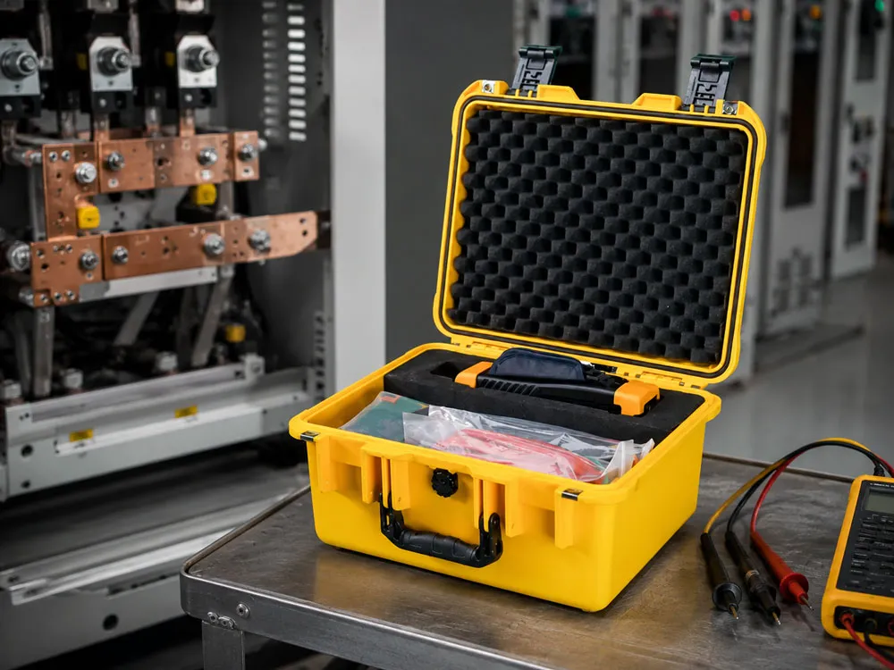
Main Causes of High Contact Resistance
High contact resistance is caused by anything that reduces real conductive contact area or increases the resistive film between conductive surfaces. The most common causes are oxidation, sulfide layers, dirt, oil, corrosion, loose fasteners, worn contacts, weak spring pressure and poor installation workmanship.
Circuit breaker contacts face additional stress because every operation creates mechanical movement. Interruption duty can cause arcing, pitting and surface erosion. If contact pressure becomes weak or alignment changes, current flows through a smaller area, causing local heating.
Busbar joints fail differently. They are often affected by bolt relaxation, incorrect torque, thermal expansion cycles, poor surface cleaning, incompatible metals, insufficient overlap area, missing washers or environmental corrosion. The ASTM B539 standard for measuring resistance of electrical connections confirms that static electrical connections are a recognized testing subject, especially where connection resistance affects reliability.
| Cause | Typical Location | Effect on Resistance | Field Symptom |
|---|
| Oxidation / Corrosion | Busbar, terminals, outdoor joints | Adds resistive surface film | Hot spot, discoloration |
| Loose Bolt Torque | Busbar joints, cable lugs | Reduces contact pressure | Temperature rise under load |
| Contact Wear / Pitting | Circuit breaker main contacts | Reduces conductive area | High micro-ohm reading |
| Contamination | Switchgear, dusty plants | Blocks clean metal contact | Unstable readings |
| Misalignment | Breaker contacts, disconnectors | Uneven current path | Phase imbalance |
| Thermal Aging | Long-term overloaded joints | Accelerates oxidation and relaxation | Repeated overheating |
Why High Contact Resistance Is Dangerous
High contact resistance is dangerous because it converts electrical energy into localized heat at current-carrying joints. As current increases, heat rises rapidly; for example, if current doubles, I²R heating increases by four times at the same resistance.
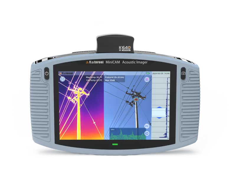
This heat can loosen bolts, damage plating, oxidize contact surfaces, age insulation, deform busbar supports and eventually cause flashover, fire or unplanned shutdown. Infrared inspection can identify many energized hot spots, and NFPA 70B maintenance discussions include infrared thermography inspection and contact resistance by millivolt drop testing as important methods for electrical connection assessment.
However, infrared inspection alone is not enough. A connection may appear normal at low load but show high resistance during a controlled micro-ohm test. This is why many maintenance teams combine thermography, visual inspection, torque checking and contact resistance testing.
How to Test Circuit Breaker and Busbar Contact Resistance
Contact resistance testing is performed by injecting a high DC test current through the contact path and measuring the voltage drop, then calculating resistance using Ohm’s law. For power equipment, low-resistance meters or micro-ohmmeters are used because ordinary multimeters cannot measure micro-ohm-level values accurately.
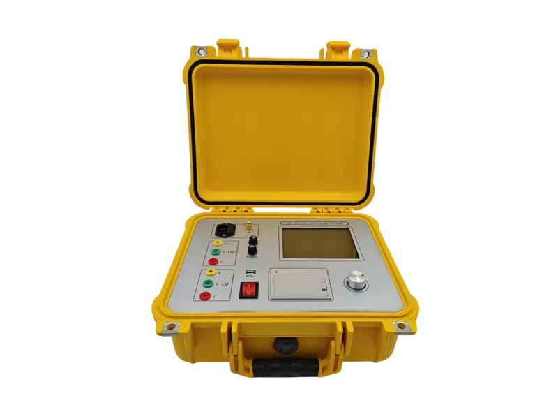
A four-wire Kelvin connection is normally preferred because it separates current leads from voltage sensing leads, reducing lead resistance error. The test current should be suitable for the equipment and maintenance procedure. Elecgene’s HLR-100 supports test currents up to 100A, while the HLR-200 supports up to 200A, making them suitable for low-resistance/high-current connection testing in field maintenance.
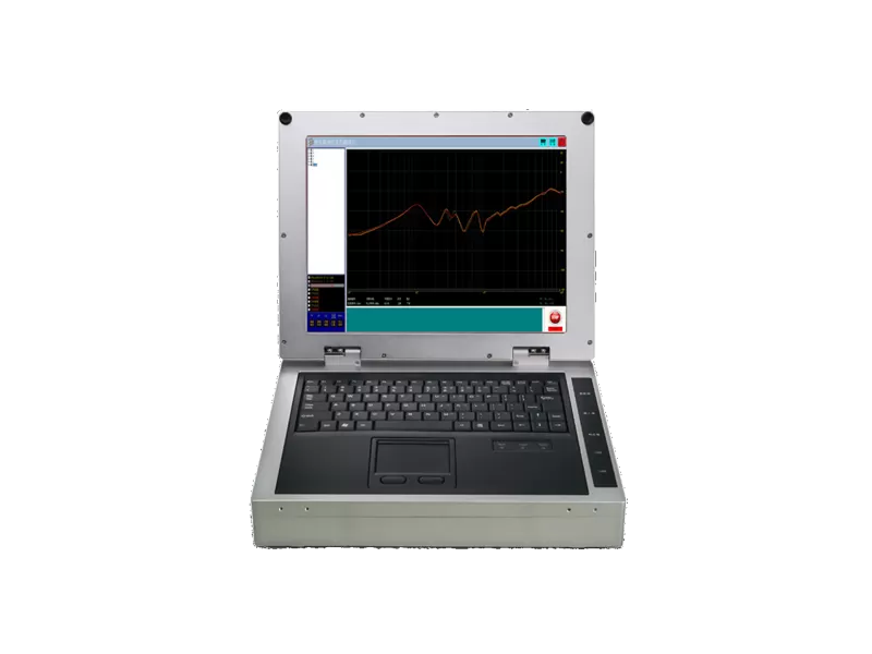
For circuit breakers, contact resistance testing should be combined with timing, travel and mechanical characteristic testing. Elecgene’s HVS-50 Circuit Breaker Analyzer is designed for complete tests on medium- and high-voltage circuit breakers, helping engineers evaluate opening/closing behavior alongside resistance results.
| Test Method | What It Reveals | Best Use |
|---|
| Micro-ohm / Contact Resistance Test | Actual conductive path resistance | Breaker contacts, busbars, disconnectors |
| Infrared Thermography | Hot spots under load | Energized switchgear and busbar joints |
| Visual Inspection | Corrosion, discoloration, pitting, looseness | First-level maintenance screening |
| Torque Check | Mechanical clamping quality | Bolted joints after shutdown |
| Breaker Timing / Travel Test | Mechanical operation quality | Circuit breaker diagnosis |
| Insulation Resistance Test | Leakage and insulation condition | Complementary safety assessment |
How to Reduce High Contact Resistance in Maintenance
Reducing high contact resistance requires clean surfaces, correct mechanical pressure, proper alignment, suitable hardware and periodic testing. The goal is not simply to tighten every bolt, but to restore stable conductive contact without damaging the joint.
For busbar joints, clean the contact surfaces according to the manufacturer’s procedure, remove oxidation where permitted, use correct hardware, apply specified torque and verify alignment. For aluminum-copper transitions, use compatible connectors and anti-oxidation practices when required by the design.
For circuit breakers, inspect main contacts, arcing contacts, contact springs, linkage condition and closing force. If contacts are severely pitted, burned or below wear limits, replacement is safer than polishing. After service work, repeat contact resistance measurements phase by phase and compare with previous records or manufacturer limits.
Elecgene micro-ohmmeters help maintenance teams trend resistance values over time. A single reading is useful, but historical comparison is more powerful because a gradual rise can reveal developing contact problems before failure occurs.
Conclusion
High contact resistance in circuit breakers and busbar joints is usually caused by oxidation, corrosion, loose mechanical pressure, contact wear, contamination, misalignment or thermal aging. The main risk is localized heating, which can accelerate damage and lead to equipment failure if not corrected.
A professional maintenance plan should combine visual inspection, infrared thermography, micro-ohm testing, torque verification and circuit breaker mechanical tests. Elecgene provides micro-ohmmeters, circuit breaker analyzers and electrical testing instruments to help utilities, substations and industrial users identify poor contacts, verify repairs and improve power system reliability.
FAQ
1. What causes high contact resistance in circuit breakers?
Common causes include worn or pitted contacts, weak contact pressure, contact misalignment, arcing damage, contamination and mechanical linkage problems.
2. What causes high contact resistance in busbar joints?
Busbar joint resistance often increases due to loose bolts, oxidation, corrosion, poor surface preparation, thermal cycling, wrong hardware or insufficient contact area.
3. Why is high contact resistance a problem?
High contact resistance creates localized heating. In high-current systems, this can damage insulation, loosen joints, oxidize metal surfaces and increase failure risk.
4. How is contact resistance measured?
It is usually measured with a micro-ohmmeter using a high DC test current and four-wire Kelvin method to measure voltage drop and calculate resistance.
5. Can infrared inspection replace contact resistance testing?
No. Infrared inspection is useful under load, but contact resistance testing gives a direct resistance value and can detect problems even when load conditions are not ideal for thermography.
6. Why choose Elecgene for contact resistance testing?
Elecgene provides handheld 100A and 200A micro-ohmmeters, circuit breaker analyzers and power testing equipment for busbar joints, breaker contacts, disconnectors and high-current electrical connections.

 English
  日本語
日本語  한국어
한국어  français
  Deutsch
  русский
  português
  العربية