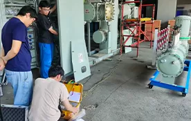
Testing protection relay pickup and operating time means verifying whether a relay starts and trips at the correct electrical threshold and within the expected time delay. This test is essential for substations, switchgear panels, industrial feeders, generators, transformers and protection schemes because relay errors can cause delayed fault clearing, nuisance trips or protection miscoordination.
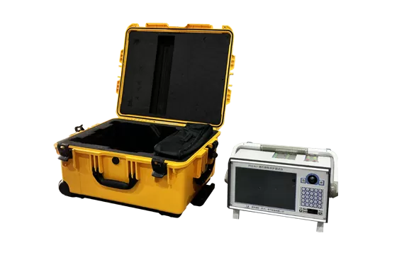
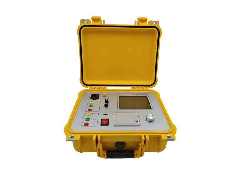
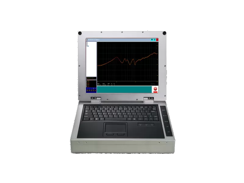
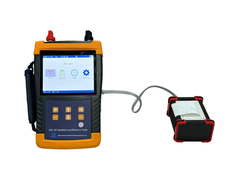
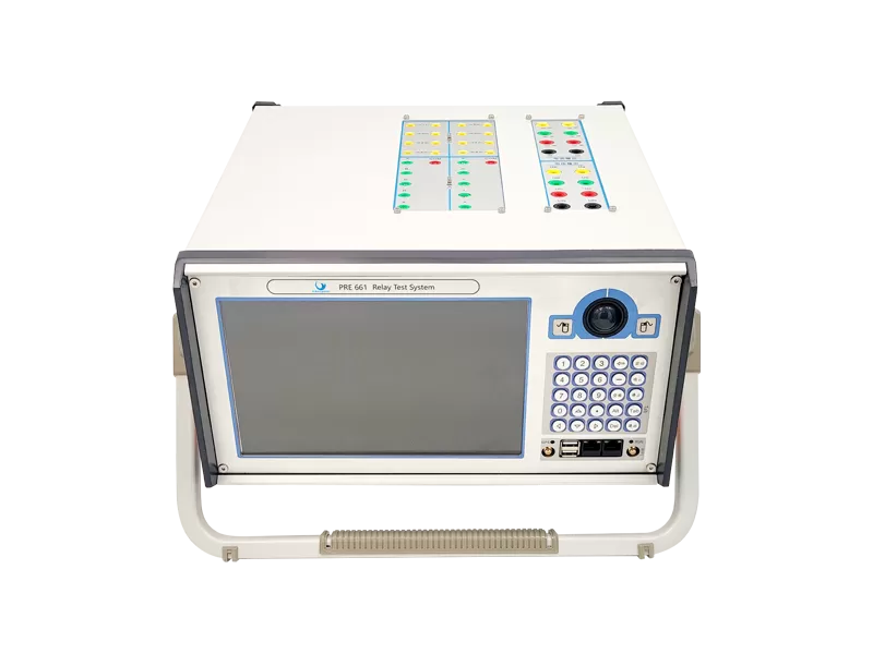
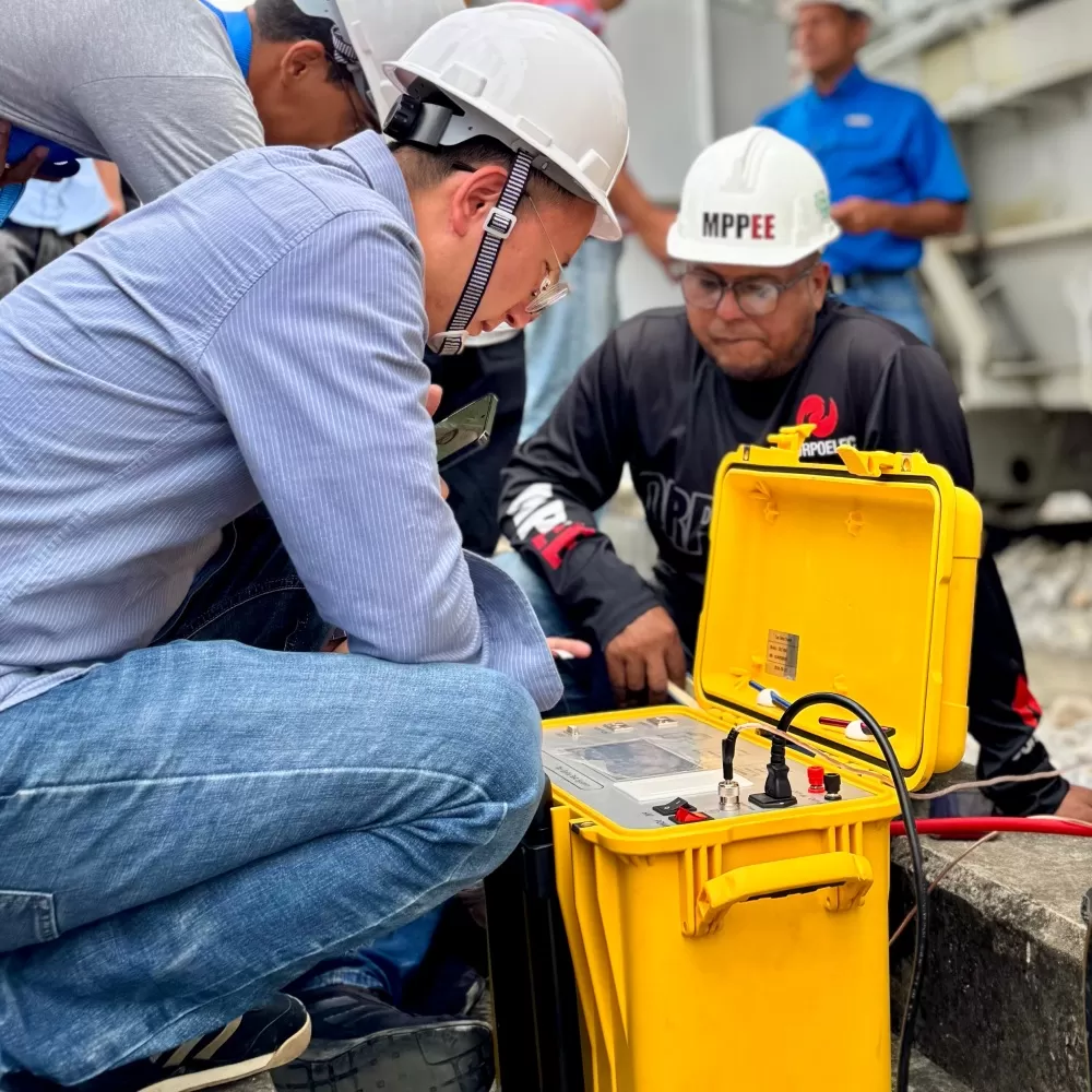
Elecgene supports relay verification with the PRE 661 6 Current and 6 Voltage Relay Test System, PRE 431 3 Current and 4 Voltage Relay Test System and HCG-1000 Pro Primary Current Injection Test System for secondary injection, primary injection and protection system commissioning.
What Are Relay Pickup and Operating Time?
Relay pickup is the minimum input quantity, such as current, voltage, frequency or impedance, that causes the protection element to operate or assert. Operating time is the interval between applying the test quantity and receiving the relay trip output or contact operation.
For an overcurrent relay, pickup may be tested by gradually increasing current until the 50/51 element asserts. For an undervoltage relay, pickup may involve decreasing voltage below the setting. For a frequency relay, pickup may be tested by changing frequency until the element starts.
Protection relay testing should follow the relay setting file, coordination study and applicable standards. IEC 60255-1 defines common requirements for measuring relays and protection equipment, while IEC 60255-151 covers functional and time-delay requirements for over/under current protection.
What Equipment Is Needed for Pickup and Timing Tests?
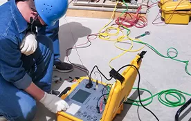
A protection relay pickup and operating time test requires a relay test set, correct wiring, relay settings, binary input monitoring, auxiliary DC supply and a safe isolation plan. For numerical relays, test software and automated templates can improve repeatability.
| Test Item | Typical Tool | What It Verifies |
|---|
| Secondary injection test | Multi-phase relay test set | Relay element pickup, timing, logic and trip contact output |
| Primary injection test | High-current injection system | CT circuit, wiring, relay input path and complete trip chain |
| Binary input timing | Relay tester timer input | Trip output contact operating time |
| Functional logic test | Relay test software | Interlock, blocking, directional and scheme logic |
| Circuit breaker trip test | Relay + breaker analyzer | Full trip circuit and breaker response |
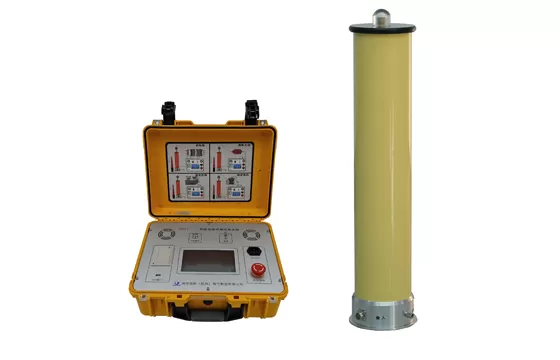
For advanced secondary testing, Elecgene’s PRE 661 provides 6-phase AC voltage 0–120 V, 6-phase AC current 0–30 A, current resolution of 1 mA, timing measurement from 0.1 ms to 9999 s, and timing resolution of 0.1 ms. For full current-path verification, Elecgene’s HCG-1000 Pro supports primary current output up to 1000 A for 60 s.
How to Test Relay Pickup Step by Step
Relay pickup testing is the process of applying a controlled electrical quantity and finding the point where the protection element asserts. The test should be performed slowly enough to avoid overshooting the pickup threshold.
First, confirm the relay setting group, CT/VT ratios, protection element, curve type, trip logic and output contact mapping. Then isolate the relay from the live system and connect the relay test set to the relay’s current, voltage and binary circuits according to the approved test plan.
For current pickup, inject a value below the setting, such as 80% or 90% of expected pickup, then ramp current upward until the relay element asserts. Record the actual pickup value and compare it with the setting tolerance. For voltage or frequency elements, use the same logic but ramp the measured quantity in the direction that causes operation.
For numerical relays, also confirm reset or dropout value. Pickup alone does not prove stable protection behavior; the element should also reset correctly when the test quantity returns to a healthy condition.
How to Test Relay Operating Time Step by Step
Relay operating time testing measures how long the relay takes to issue a trip signal after the fault quantity is applied. The timing test should use a defined multiple of pickup or a specified test point from the relay curve.
For definite-time elements, inject a test quantity above pickup and measure the time from injection start to trip contact operation. For inverse-time overcurrent elements, choose test currents such as 2×, 5× or 10× pickup, then compare the measured operating time with the relay curve and time multiplier setting.
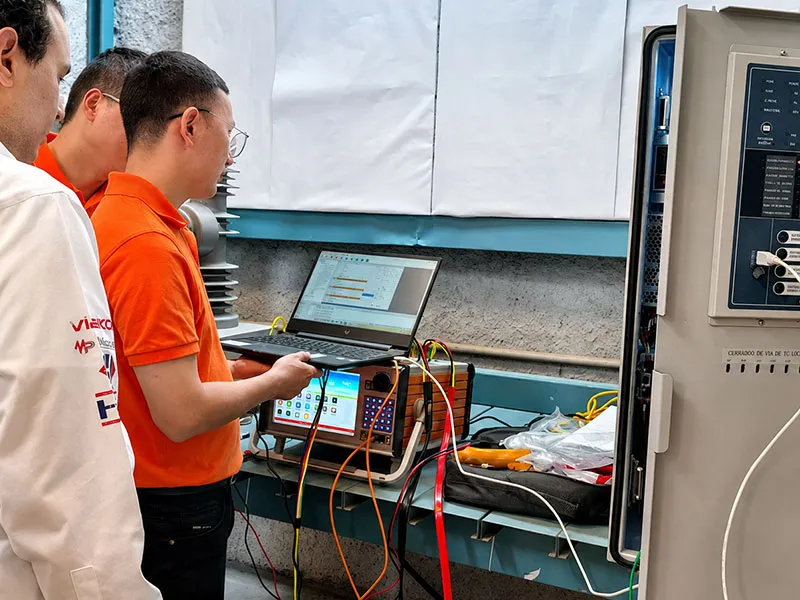
The binary input of the relay test set should be connected to the trip output contact, and the timer should start at injection and stop when the output changes state. Elecgene’s PRE 661 is suitable for this type of test because it combines multi-phase outputs with isolated binary inputs and built-in time measurement.
Field acceptance testing should also consider commissioning requirements. ANSI/NETA ATS is used to assess whether electrical power equipment and systems are suitable for initial energization, so pickup, timing and trip verification should be documented as part of the commissioning record.
How to Interpret Test Results and Avoid Common Errors
Interpreting pickup and operating time results means comparing measured values with relay settings, manufacturer tolerance, coordination study requirements and previous test records. A result can be electrically correct but still unsuitable if it does not match the protection coordination plan.
Common errors include wrong CT ratio, wrong setting group, incorrect phase angle, disabled trip output, wrong binary input polarity, unstable auxiliary DC supply, poor test lead connection and testing the wrong protection element. For directional or distance relays, current and voltage phase relationship is especially important.
A practical acceptance table may look like this:
| Result Area | Good Practice | Risk if Ignored |
|---|
| Pickup value | Compare with setting and tolerance | Element may underreach or overreach |
| Operating time | Compare with curve and time delay | Fault clearing may be too slow or too fast |
| Reset value | Confirm dropout or reset behavior | Relay may chatter or remain asserted |
| Trip output | Verify correct contact operation | Relay operates but breaker may not trip |
| Test report | Record settings, wiring, values and results | Future troubleshooting becomes difficult |
Elecgene’s Power Protection Testing solutions are used in substations, switchboards, power companies and industrial facilities to verify protection system reliability, reduce downtime and improve testing efficiency.
Conclusion
Protection relay pickup and operating time testing verifies whether the relay operates at the correct threshold and within the expected time. Pickup testing confirms sensitivity, while operating time testing confirms coordination and trip performance.
A professional test plan should include setting review, safe isolation, correct injection method, binary trip contact timing, result comparison and complete documentation. Elecgene provides secondary injection test kits, relay test systems, primary current injection equipment and power protection testing solutions to help engineers perform reliable commissioning, maintenance and troubleshooting for modern protection systems.
FAQ
1. What is relay pickup?
Relay pickup is the minimum current, voltage, frequency or other measured quantity that causes a protection element to assert or start.
2. What is relay operating time?
Relay operating time is the time between applying the test quantity and receiving the relay output or trip contact operation.
3. What is the best method for relay pickup testing?
Secondary injection is usually the most direct method because it allows engineers to inject controlled current or voltage into the relay and measure the exact pickup point.
4. When should primary injection be used?
Primary injection is useful when engineers need to verify the complete current path, including CTs, wiring, relay input and trip chain.
5. Why does operating time need to be tested at different current multiples?
Inverse-time relays operate faster at higher fault currents, so testing at selected multiples of pickup helps verify the relay curve and time multiplier setting.
6. Why choose Elecgene for relay testing?
Elecgene provides multi-phase relay test systems, primary current injection systems and power protection testing equipment for substations, switchgear, industrial plants and utility maintenance teams.

 English
  日本語
日本語  한국어
한국어  français
  Deutsch
  русский
  português
  العربية