| Category | Details |
| Test Time | 2025. 2. 27 |
| On-site Tester | Gao Wenhao |
| Environment of the Day | Sunny |
| Test Location | Jiayuguan City |
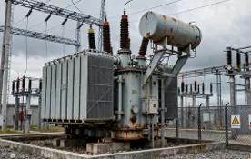
| Basic On-site Information | Test Object Type: Transformer Voltage Level: 6kV |
| Test Item | Transformer Low Voltage Short-circuit Impedance Test |
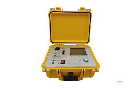
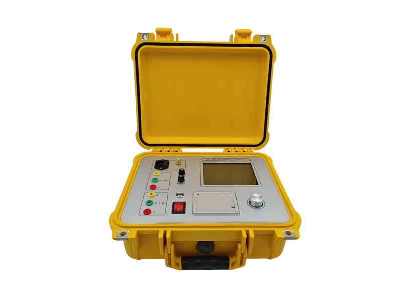
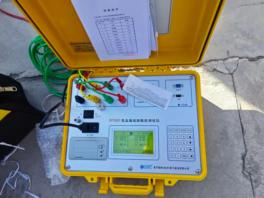
| Instrument Used | SIT-600 |
| Test Data | Qualified |

Test Purpose
Transformer low voltage short-circuit impedance testing is used in factory, overhaul, preventive, and handover tests of power transformers (single-phase or three-phase).
The principle is to conduct an on-site short-circuit impedance (%) test on the power transformer and compare it with the nameplate value or factory value. This can detect defects such as winding displacement and deformation caused by severe fault currents during transportation, installation, and operation after the factory test (The "2000 China International Conference on Electricity Distribution" stipulates that a short-circuit variation exceeding ± 3% should be considered a significant change).
The low voltage short-circuit impedance test method requires no external voltage regulator and only needs one-time wiring. By simply inputting the parameters, it can automatically conduct a three-phase test and calculate the impedance error percentage. The test results are intuitive and can quickly determine whether there is winding deformation in the transformer.
Test Process
1) Test Preparation Work
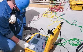
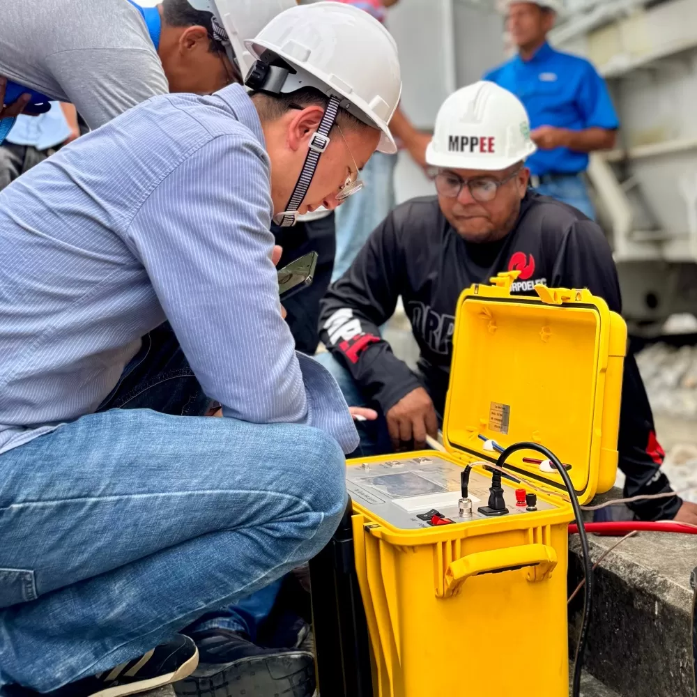
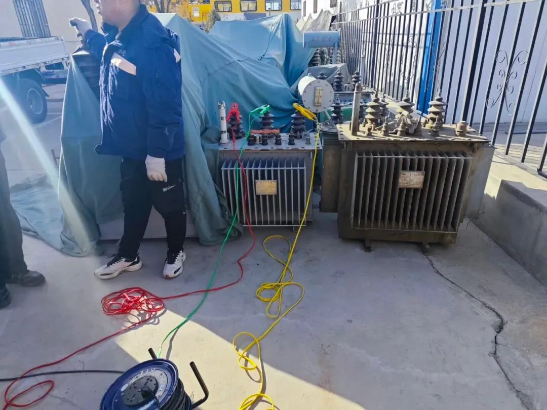
The on-site test was conducted in a warehouse, an appropriate power supply was located, and the test instrument was grounded.
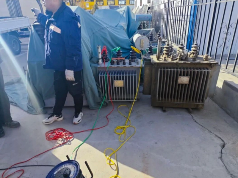
The three phases of the transformer's low voltage side were short-circuited with short-circuit wires, ensuring a solid connection. The equipment's output was connected to the transformer's high voltage side A, B, and C correspondingly using yellow, green, and red clips.
The test wiring diagram is shown in the figure below:

2) Test Process
Check that there are no issues with all the test wiring; connect the power cord, turn on the instrument, enter the test interface, and set the parameters according to the transformer nameplate.
After the setup is complete, press the "Ent" button to start the test, choose to measure a three-phase transformer, select the automatic mode test, and then choose the wiring method.
Press the "Ent" key to initiate the measurement. The instrument automatically applies current to the AB, BC, and AC phase windings in sequence to lock in the three-phase measurement values. After the measurement concludes, the instrument automatically calculates the impedance error data.
3) Result Judgment
Transformer Nameplate Impedance: 3.99%
Measured Impedance: 3.56%
Impedance Error: -10.67%
Comparisons are generally made against historical data and factory test reports. The following is excerpted from the standard "GB 1094.1-2013 Power Transformers Part 1: General", specific to transformers:
Test Summary
When testing the short-circuit impedance, the transformer capacity must be entered correctly. If the transformer capacity is incorrect, the resulting impedance test will also be incorrect.
The test must be performed with the transformer set to the exact same tap position as indicated in the report.