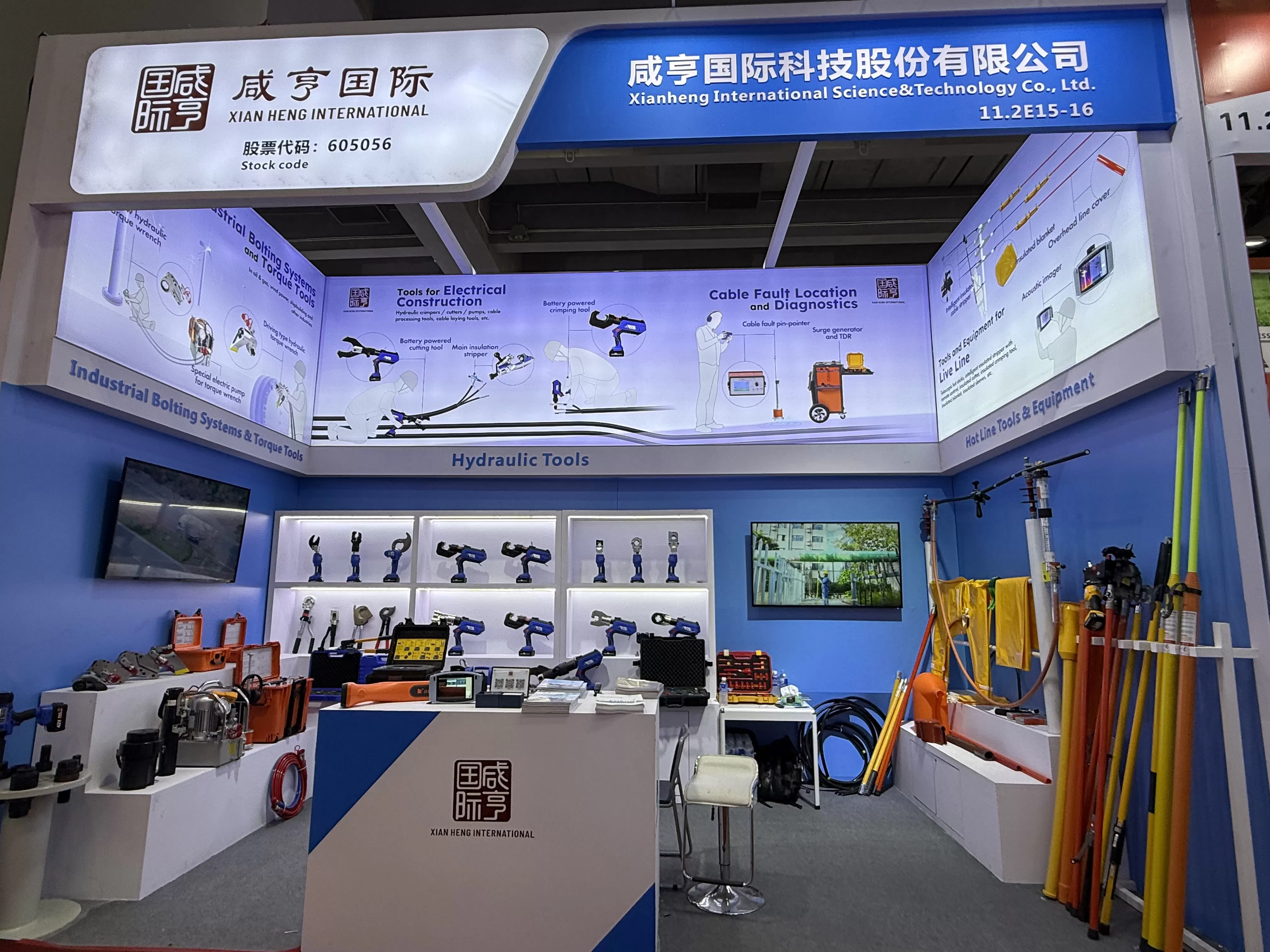
PART 1: Main Information of On-site Test
Test Time: 2025.4.16
On-site Tester: Gao Wenhao
Weather: Sunny
Test Location: Jiujiang
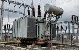
Test Object Type: Transformer
Voltage Level: 10KV
Test Items: Transformer DC resistance, turns ratio, energy efficiency level, and insulation resistance tests
Instrument Used: MFTS-5
Test Data: Yes
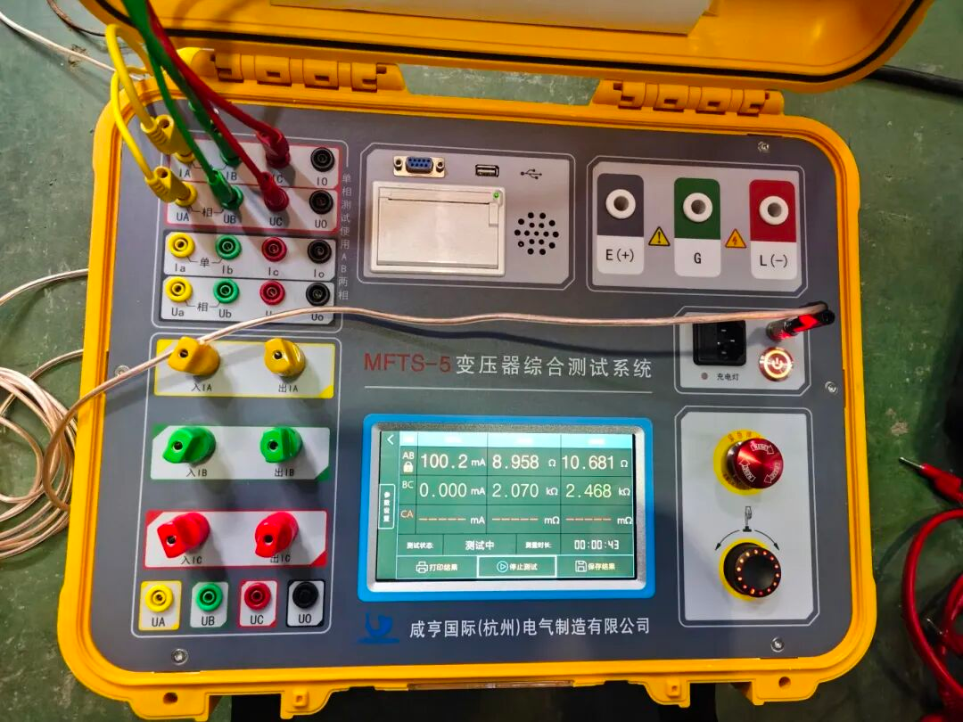
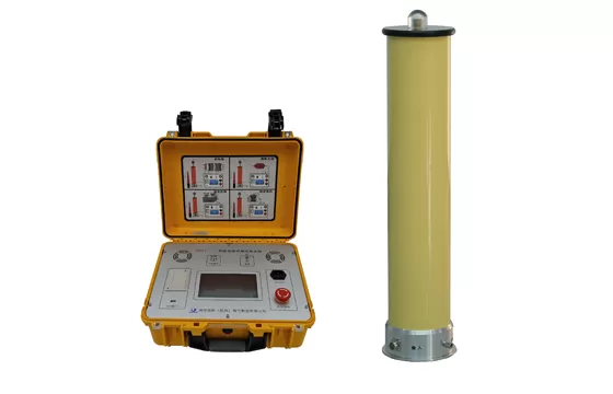
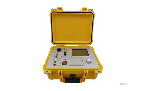
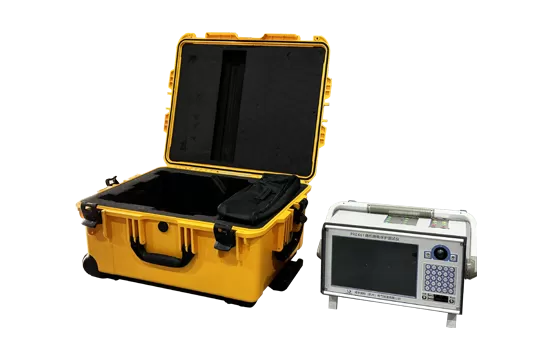
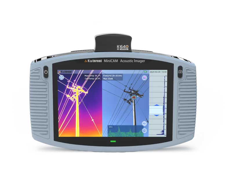
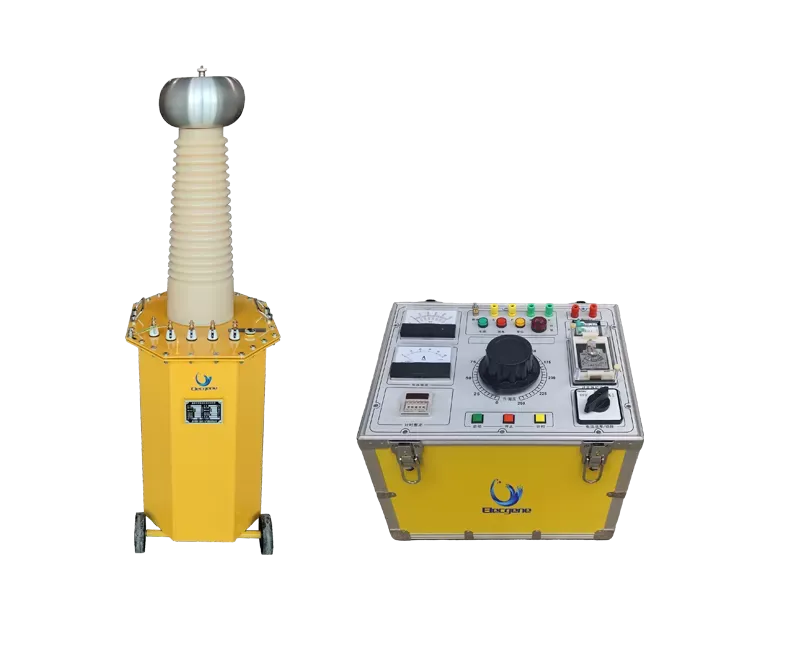
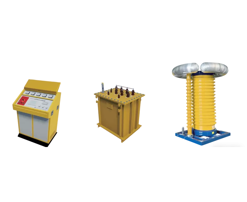
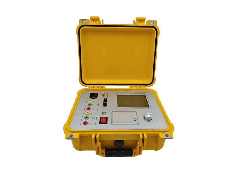
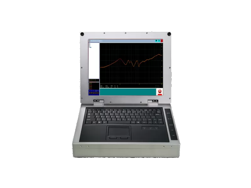
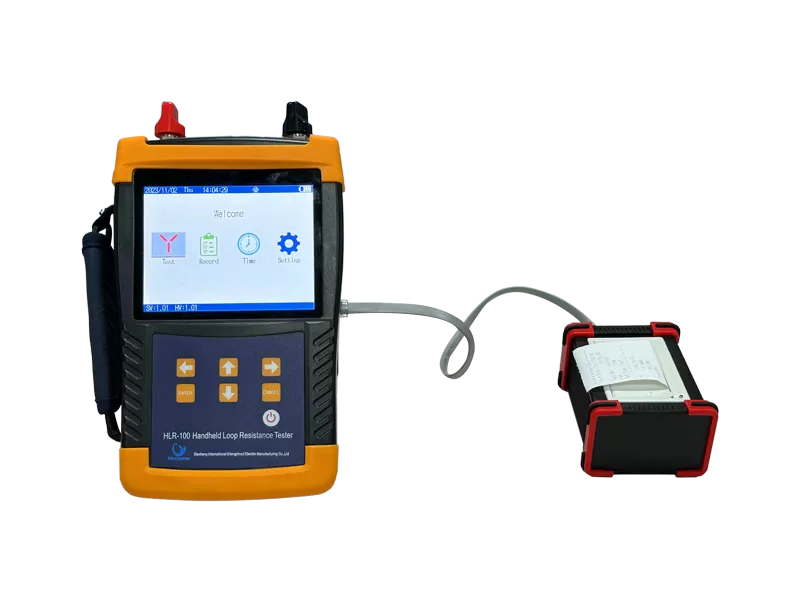
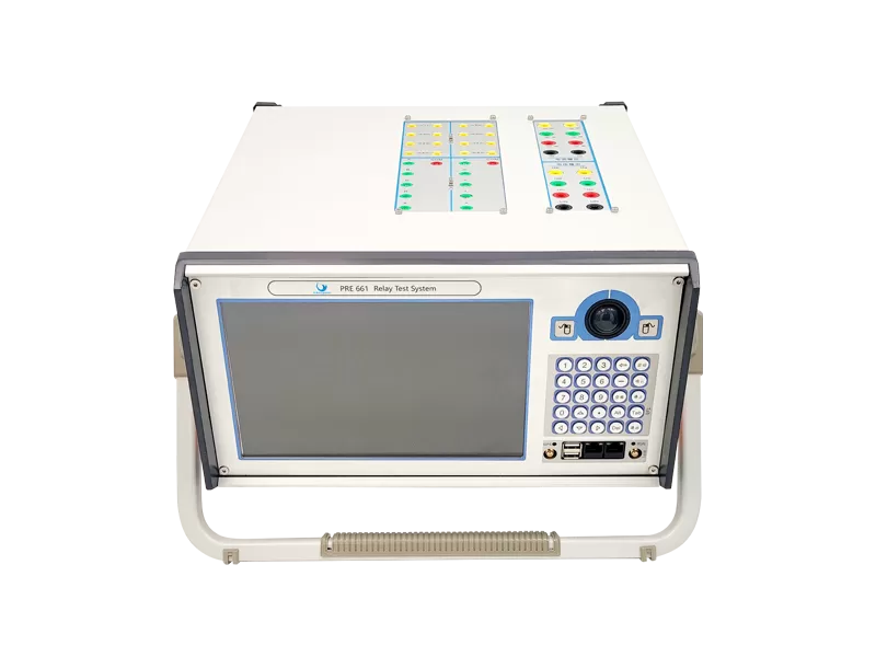
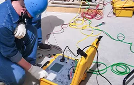
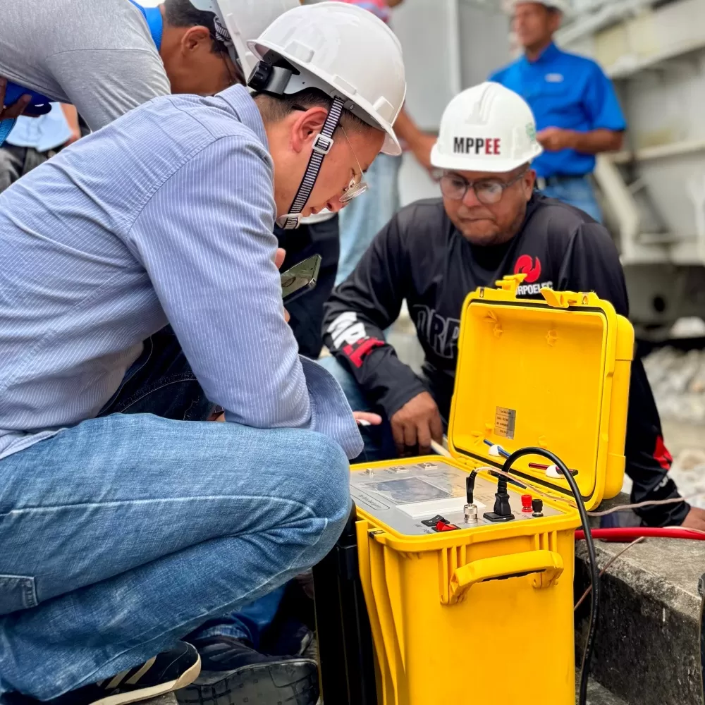
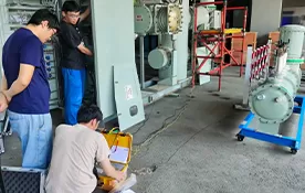
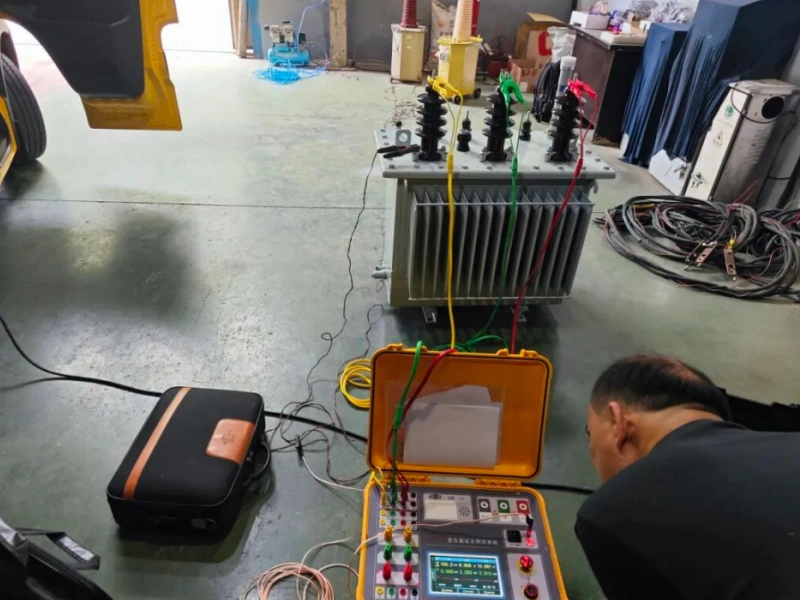
Pictures of On-site Test Instruments
PART 2: Test Purpose
For the power system, the transformer is the core equipment, so its long-term and reliable operation is related to the stability and reliability of the entire system.
Currently, the distribution transformer loss and energy efficiency level test, transformer DC resistance test, transformer turns ratio and connection group test, and transformer insulation resistance test are mandatory items for transformer outage maintenance. To complete these tests and operations, it is necessary to separately configure a transformer loss tester, a transformer DC resistance tester, a transformer turns ratio and group tester, and a transformer insulation resistance tester, meaning four kinds of instruments must be carried for each test. Because they are four independent instruments, each is equipped with dedicated test cables, requiring separate testing processes and frequent wiring changes, which wastes a lot of manpower, material resources, and working hours.
Our company has innovatively developed a multi-in-one transformer comprehensive test system powered by a large-capacity lithium battery. We only need one set of equipment to complete the testing of four items without the need to frequently disconnect and connect test cables, greatly improving work efficiency and saving user costs.
PART 3: Test Process
1. DC Resistance Test
Clamp the yellow, green, and red test line clips of the instrument onto the A, B, and C phases of the high-voltage side of the transformer, respectively, and insert the current line and voltage line plugs at the other end of the test line into the corresponding interfaces of the instrument.
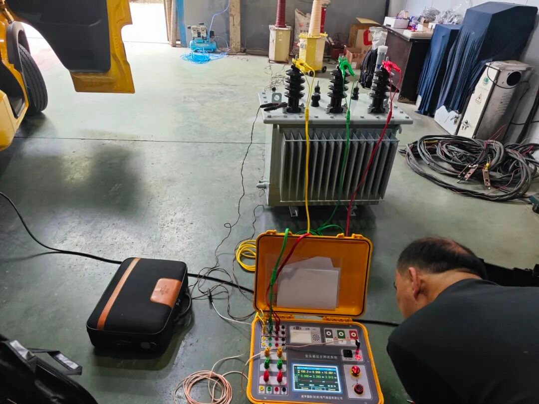
Check that all test wiring is correct; turn on the instrument and enter the DC resistance test; set the test phase, converted temperature, tap position, test current, etc., and start testing after parameter setting is completed.
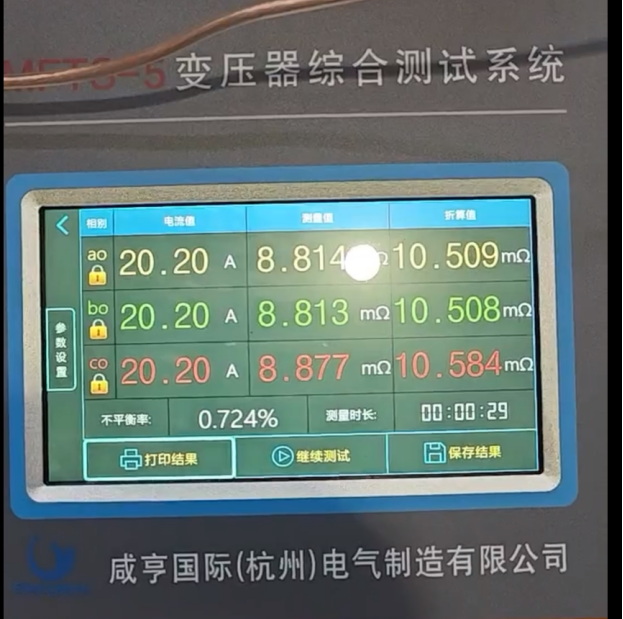
Comparing the test result data with the regulations, it can be seen that the unbalance rate is lower than the standard value, and the transformer DC resistance test is qualified. The following standard regarding the transformer is excerpted from "DL/T 596-2021 Preventive Test Code for Electric Power Equipment".
2. Turns Ratio Test
Fix the test line clips correspondingly on the high-voltage side and low-voltage side of the transformer. (Friction should be applied back and forth during fixation to ensure good contact). Connect the other end of the test line to the corresponding wiring port on the instrument end, high-voltage side to high-voltage side, low-voltage side to low-voltage side; the high and low-voltage sides must never be reversed.
Turn on the instrument switch, proceed with settings, select the three-phase test, and after selecting the test method, enter the parameter setting interface. Set the parameters according to the transformer nameplate (rated high and low voltage side voltage, rated tap, tap step, and connection group), and start measuring after setting.
Generally, compare with historical data and factory inspection reports. Comparing the test result data with the regulations, it can be seen that the voltage ratio is lower than the allowable deviation value, and the transformer turns ratio test is qualified. Test data judgment refers to "DL/T 596-2021 Preventive Test Code for Electric Power Equipment".
3. Energy Efficiency Test
First, use a dedicated short-circuit wire to short-circuit a, b, and c on the low-voltage side of the transformer, ensuring a good short circuit.
Connect the yellow, green, and red clips output by the device to the A, B, and C phases on the high-voltage side of the transformer correspondingly. The thicker wire at the instrument end connects to the current hole, and the thinner wire connects to the voltage hole.
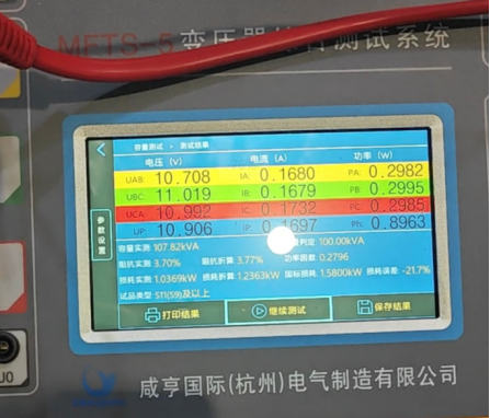
Turn on the machine for parameter setting. In the capacity test setting, set the corresponding test parameters based on the transformer nameplate information, including voltage level, connection method, and short-circuit impedance. After setting, start the test.
4. Insulation Resistance Test
To test the insulation resistance of the transformer from high to low and to ground, first short-circuit the high-voltage side and low-voltage side of the transformer with bare copper wires respectively. Apply voltage to the high-voltage side, and connect the low-voltage side to the transformer shell for grounding.
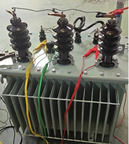
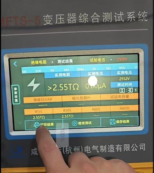
After checking that all wires are connected, select the 2500V test voltage on the instrument to test, and stop when the resistance value stabilizes.

 English
  日本語
日本語  한국어
한국어  français
  Deutsch
  русский
  português
  العربية