I. On-site Test Main Information
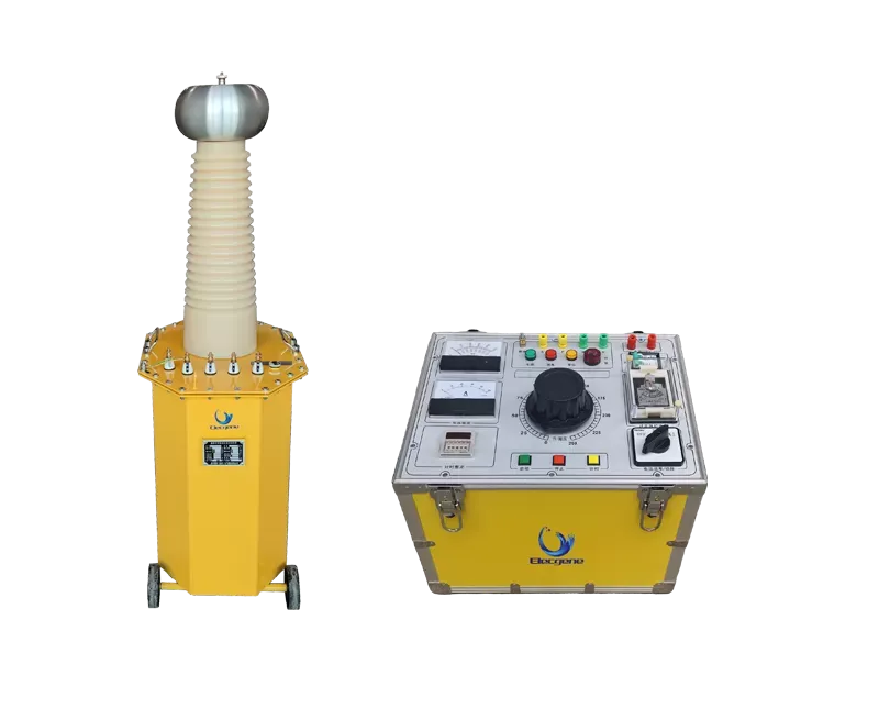
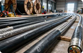
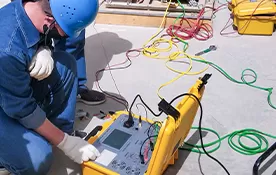
This report documents an on-site AC withstand voltage test performed on a 20 kV XLPE cable in Xiaoshan, Hangzhou. The test was carried out with an RTE-30 variable-frequency series-resonant test set to verify the insulation integrity of the cable before energization.
1. Basic Information
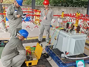
Test date | 2024-10-25 | Test engineer | Gao Wenhao |
Weather | Sunny | Test location | Xiaoshan, Hangzhou |
Specimen type | XLPE cable | Voltage class | 12/20 kV |
Test item | AC withstand voltage test | Instrument used | RTE-30 |
Test data | Phase A broke down; phases B and C passed the withstand voltage test. |

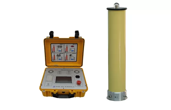
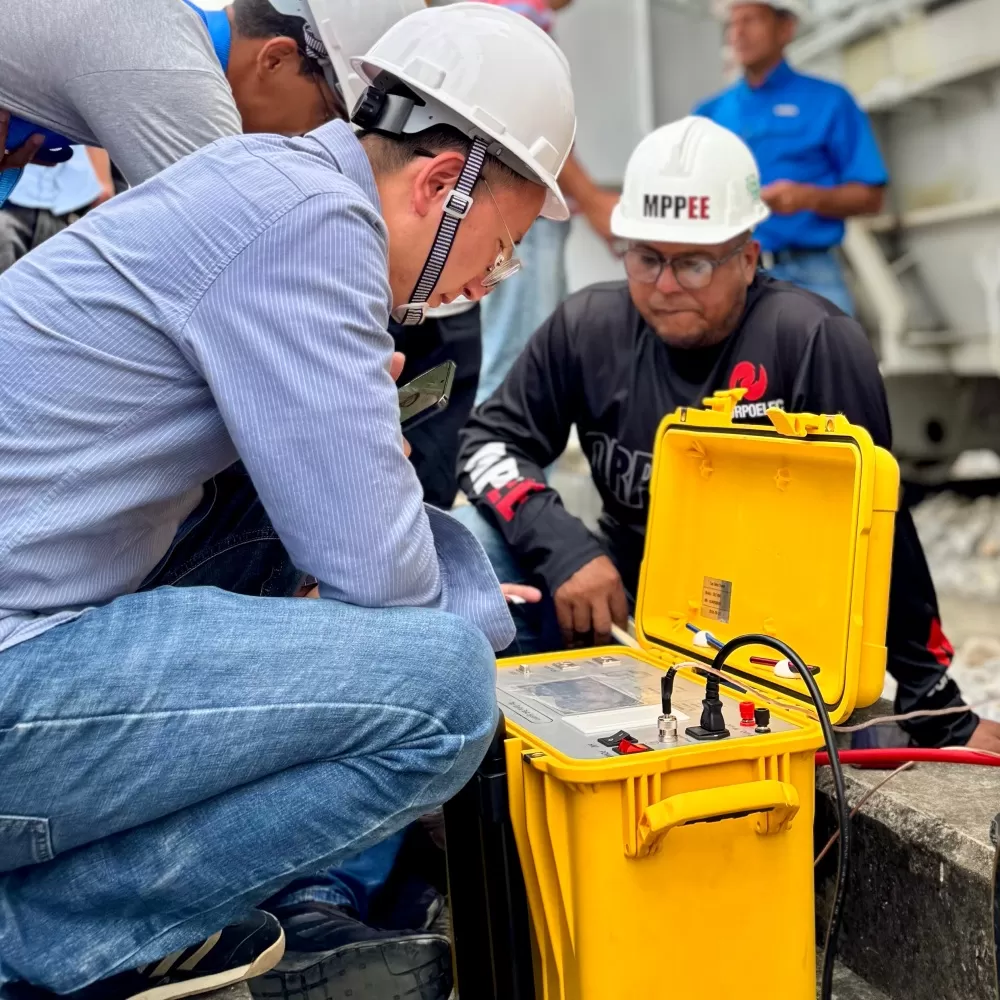
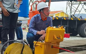
Figure 1 RTE-30 variable-frequency series-resonant test set used on site
II. Test Procedure
Step 1: Test Preparation
1. A generator was prepared as the outdoor power supply, and safety barriers, warning signs, and personal protective equipment were set up around the test area.
2. Before applying the AC withstand voltage, cable insulation resistance was measured. Phase A showed 200 MΩ, which was lower than the other two phases; phases B and C were normal.
3. The cable under test was 3,500 m long, 12/20 kV, 300 mm². From the cable parameter table, the capacitance was calculated as C = 1.1113 µF. With a test voltage of 24 kV, the test scheme adopted six reactors in parallel. Each reactor had an inductance of 80 H, giving a total inductance L = 13.3 H. The resonant frequency was calculated as f = 1 / (2π√LC) = 41.35 Hz, and the test current as I = 2πfCU = 6.929 A.

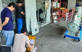
Figure 2 On-site test area with safety barriers and generator power supply

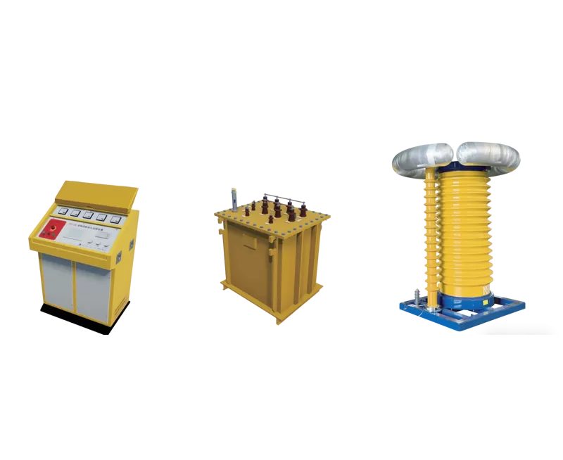
Figure 3 Six reactors connected in parallel
Step 2: Test Process
1. The output of the series-resonant control cabinet was connected to the excitation transformer input; the excitation transformer output was connected to the bottom of the reactors; the top of the reactors was connected to the voltage divider; the voltage divider was connected to the test object; and the divider was connected to the main unit through a signal cable.
2. The instrument and the test object were grounded, and the control cabinet was connected to the power supply.
3. Reactor parameters, divider ratio, excitation-transformer ratio, test voltage, and withstand time were entered into the control host.

Figure 4 Series-resonant test wiring
Step 3: Result Evaluation
1. Around the calculated resonant frequency of 41.35 Hz, the actual resonant frequency was found (41 Hz–42.66 Hz). The voltage was then raised to the test voltage of 24 kV and maintained for 15 minutes.
2. At the 13th minute of the withstand period, phase A flashed over. After switching off the test set and discharging the cable, the insulation resistance of phase A was re-measured and found to be 0, indicating that phase A had broken down to ground. The ground fault must be cleared before the withstand voltage test is repeated.
3. Phases B and C passed the AC withstand voltage test.

Figure 5 Full on-site AC withstand voltage test setup

Figure 6 Test instrument screen showing successful withstand voltage result
III. Test Summary
During service, electrical equipment insulation is continuously subjected to electric field, temperature, and mechanical vibration, which gradually cause aging. This aging can be either general or local, leading to defects. Because the AC withstand voltage test voltage is usually higher than the operating voltage, equipment that passes the test has a substantial safety margin. Therefore, AC withstand voltage testing is an important means of ensuring the safe operation of power equipment.

 English
 日本語
 한국어
 français
 Deutsch
 русский
 português
 العربية