I. On-site Test Main Information
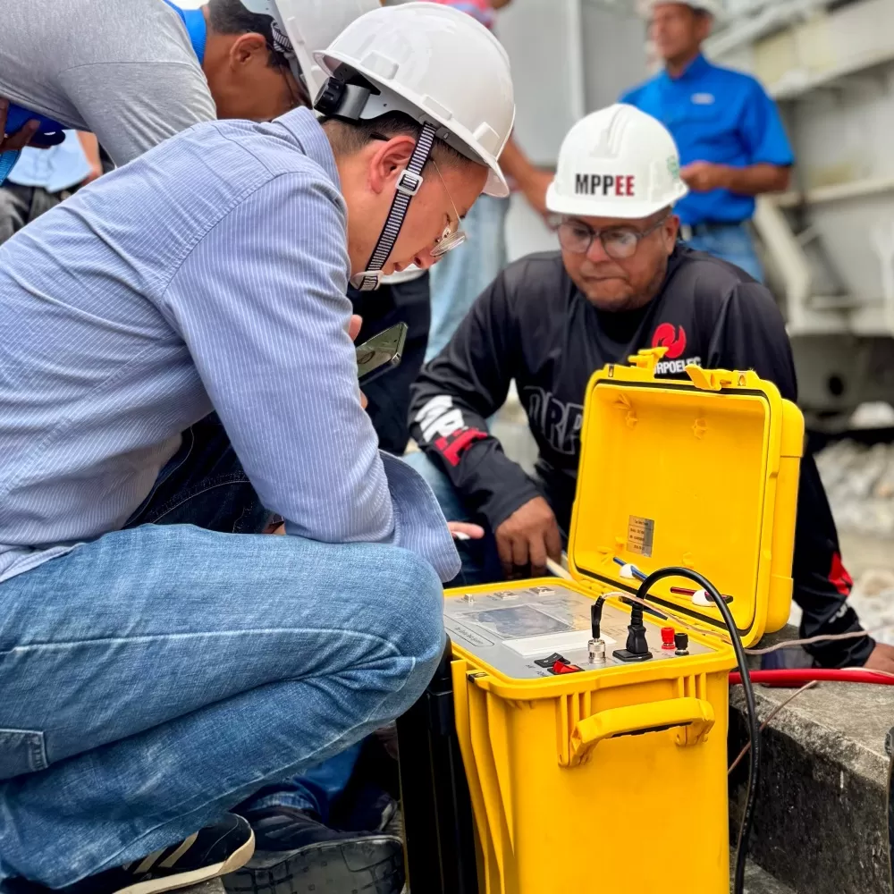
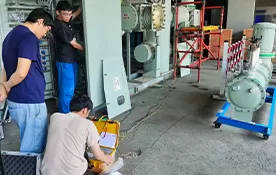
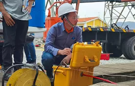
This report presents a 380V battery bank capacity test performed at a West-East Gas Pipeline station using the Xianheng HXZF-50 (60030A) battery charge/discharge integrated machine.
1. Basic Information
Test date | 2024/09/05 | Tester | Huo Qi |
Weather | Sunny | Location | A West-East Gas Pipeline station |
On-site condition | 380V battery bank capacity verification |
Instrument used | HXZF-50 (60030A) |

Figure: HXZF-50 (60030A) battery charge/discharge integrated machine
II. Test Purpose
The battery charge/discharge integrated machine performs capacity discharge tests to detect the operating status of the battery bank and identify aged or degraded cells. Its built-in cyclic charge/discharge function can activate lagging cells, increase capacity, and extend service life. During charge/discharge, the system collects individual cell voltages in real time via wireless/wired/CAN communication, enabling rapid and accurate capacity assessment while protecting cells from over-discharge or over-charge damage.
III. Test Method
The equipment consists of the main unit, wireless individual-cell detection modules, and charge/discharge cables. After the battery bank under test is isolated from the system, it is connected to the main unit. The quick connectors of the test cables are inserted into the quick sockets of the instrument by color: battery positive (red), battery negative (black).
Wiring sequence:
1. Connect battery positive to the positive terminal of the battery bank.
2. Connect battery negative to the negative terminal of the battery bank.

Figure: Test wiring diagram
Instrument power supply:
1. Discharge: AC220V or AC380V AC supply line can be connected.
2. Charge: a dedicated charging power cable must be connected, with the other end to the distribution box, input AC380V (A/B/C/N/PE), and the power must not be lower than 30kW.
Module connection:
For 12V individual cells: the red wire and the shortest yellow wire clip at the same position, i.e., the positive terminal of the 4th cell, ensuring they are connected in sequence as shown below.

Figure: Individual cell module wiring
Parameter setting: On the main test interface, parameters can be set. Click test type and select "Charge" or "Discharge". After setting, click "Save" and proceed.
Start test: After parameter configuration is complete, click Save to enter the test interface, then click the "Start" button to begin the test.
IV. Test Procedure
First, isolate the battery bank under test from the system, and insert the quick connectors of the discharge test cables into the quick sockets of the instrument by color: battery positive (red), battery negative (black).

Figure: Charge/discharge current cables

Figure: Battery cell modules
After connecting the discharge test cables and modules, set the parameters. The individual cell voltage is 12V, with 32 cells in total and a capacity of 75Ah. According to DL/T 724-2021, the pre-discharge current is I10 = 75Ah / 10h = 7.5A.

Figure: Individual cell data

Figure: Discharge capacity curve

Figure: Test result analysis
After the capacity test, the batteries were qualified and the site was restored to its original state.
V. Test Summary
Batteries in long-term float-charge operation will eventually be covered by a thick oxide film on the electrodes, causing anode plate passivation. The internal resistance will gradually increase, and the actual capacity will be much lower than the rated capacity. Valve-regulated batteries are "maintenance-free" only in the sense that no water, acid, or electrolyte replacement is needed; however, routine inspection and maintenance are indispensable. Under-charge, over-charge, over-discharge, and excessively high ambient temperature during operation will all degrade battery performance. Capacity discharge testing can objectively and accurately measure the true capacity of the battery bank. At the same time, appropriate charge/discharge cycling can extend service life and ensure the reliability of the DC system operation.

 English
 日本語
 한국어
 français
 Deutsch
 русский
 português
 العربية