I. Overview
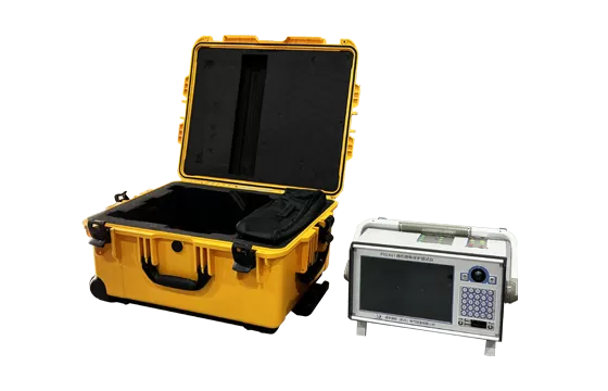
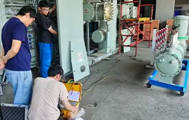
This report summarizes a 110kV substation load-simulation relay protection vector check test carried out at a 110kV substation using the PRE 3000 relay protection vector check set.
1. Basic Information
Substation name | XX 110kV substation | Test date | 2024.08.31 |
Main transformer | SSZ11-20000/110, 20MVA, 110/35/10kV |
110kV bays | 110kV Jin-A line, 110kV A-Man line, 110kV main transformer |
110kV connection | Single busbar | CT ratio | 400/5 |
Weather | Sunny | Temperature | 15 ℃ |
Test unit | Xianheng International Technology Co., Ltd. |
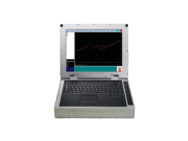
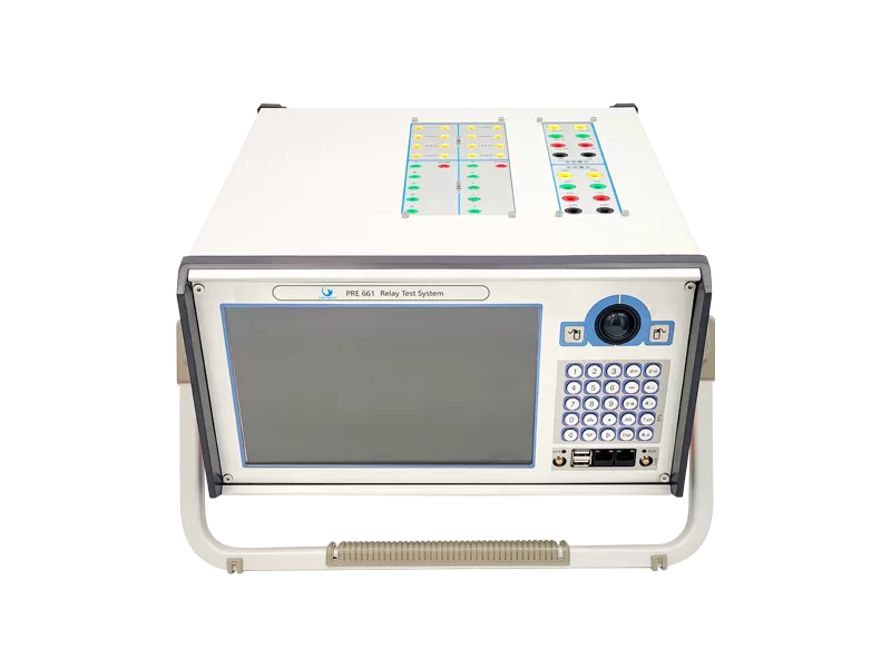
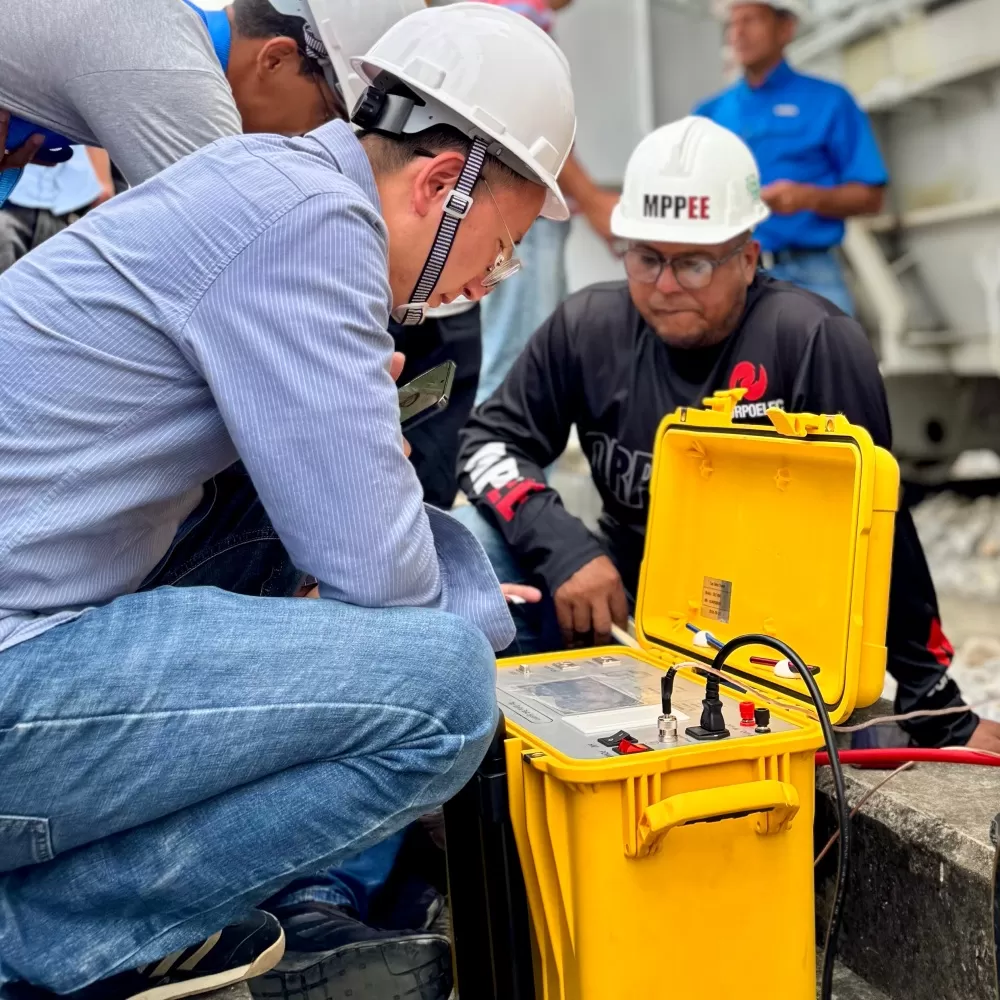
Test equipment | PRE 3000 relay protection vector check set |
Test items | 1. Full-station PT checks at all voltage levels. 2. Load-simulation vector check. |
Test results | PT ratio and phase correct; current ratio and phase correct; voltage phases show 5° deviation in all three phases. |

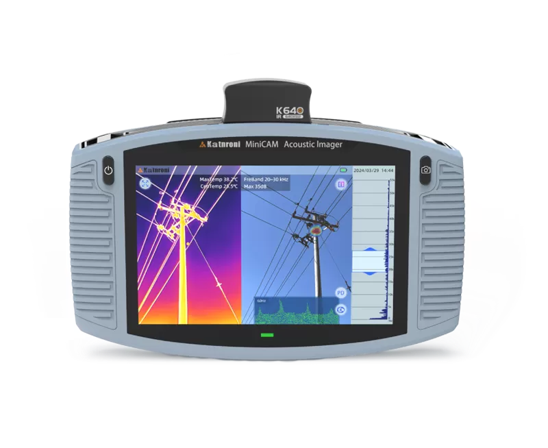
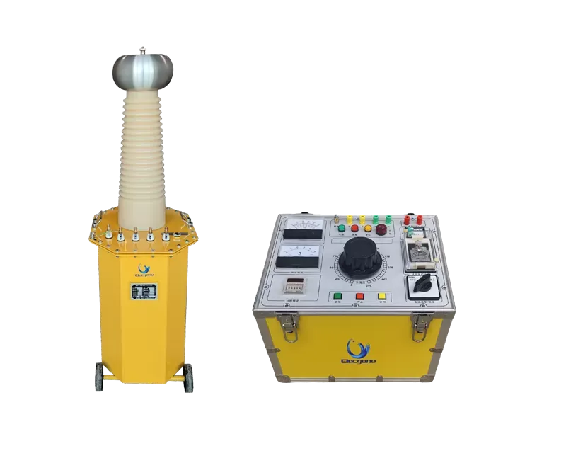
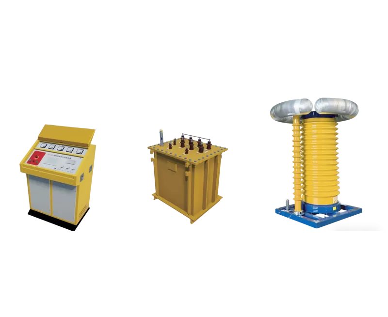
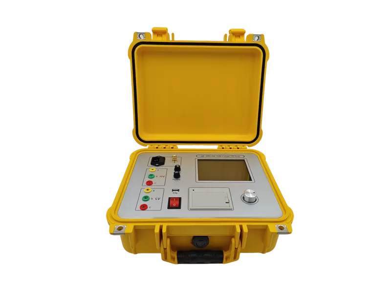
Figure: PRE 3000 relay protection vector check set
II. Test Purpose
Relay protection is the first line of defense for power grid security and stability, and a key link in preventing accident escalation. The correctness of relay protection vectors is crucial for correct relay operation and is a mandatory check during new equipment energization.
III. Test Principle
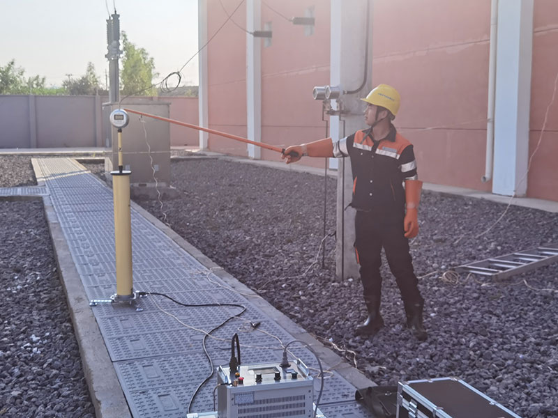
The method applies voltage to the primary side of the voltage transformer and current to the primary side of the current transformer, simulating line/busbar/transformer primary currents and operating voltages. This allows the relay protection vector check for all protection devices in a new substation or extension bay to be completed before energization.
IV. Reference Standards
DL/T 995-2016 "Inspection Code for Relay Protection and Power System Security Automatic Equipment"
"Load-Simulation Relay Protection Vector Check Test Guide"
V. Test Equipment
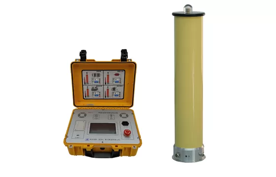
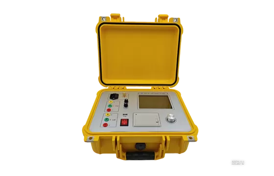
The PRE 3000 relay protection vector check set simulates and replaces line, busbar, and transformer load checks. It outputs high voltage and high current to primary equipment, enabling verification of secondary vector correctness and providing a basis for ensuring the correctness and integrity of relay protection devices and secondary circuits. It also solves the problem that previous test equipment could not output sufficiently high voltage to verify the wiring correctness of main transformer bushing CT secondary circuits. It is suitable for new, reconstructed, and expanded substations up to 500kV.

Figure: 110kV substation primary connection and test injection points
VI. Preparations
1. Primary and secondary equipment installation, commissioning, and testing have been completed and accepted.
2. Complete and project-accurate drawings and documentation are available.
3. Before the test, ensure all CT secondary circuits are not open, reliably grounded, and correctly connected; ensure all PT secondary circuits are not shorted, reliably grounded, and correctly connected.
4. Before the test, disconnect and ground the test line, and confirm with relevant personnel that test voltage/current will not be fed into transmission lines, while preventing induced voltage on the test line.
VII. Test Process
(1) Line and busbar simulated load relay protection vector check
Primary current injection
To reduce the impedance of the primary current loop, a line bay located roughly in the middle of the busbar is selected as the current injection point. The test set output is adjusted so that the CT secondary output current is not less than 20mA. The operating mode is changed sequentially to complete the simulated load vector check for the remaining lines and busbars.
Taking the 110kV Jin-A line and A-Man line as examples, the simulated line load vector check is performed. The current is injected at the Jin-A line disconnector, returning through the A-Man line grounding switch, with the earth as the return conductor.

Figure: Primary current injection at Jin-A line disconnector
Phase reference
Option 1: primary voltage injection. The busbar PT in the same busbar section as the current injection bay is selected as the voltage injection point. The test set output is adjusted so that the PT secondary output voltage is not less than 1V, serving as the phase reference for the simulated load test. The PT primary side must be disconnected.
The voltage source and current source test sets communicate wirelessly and output primary voltage and primary current synchronously via wireless or GPS synchronization.

Figure: Synchronous primary voltage and current output
Option 2: secondary voltage injection. The current source test set can output three-phase primary current and secondary voltage simultaneously. Therefore, provided the full-station PT phase check is correct, a method combining simulated primary current and secondary voltage can be used. The primary current injection wiring remains unchanged, and the three-phase voltage output (3×0–120V) of the current source test set is connected to the PT secondary terminal box or secondary voltage terminal block, using the internal voltage phase of the device as the reference.

Figure: Secondary voltage injection method
Set the device output voltage and current so that the secondary voltage reaches 1V (or rated voltage when using PT secondary voltage injection) and the secondary current exceeds 20mA. After starting the test, check the secondary current value and vector on the relay protection device.

Figure: Secondary data view
Similarly, for other bays the test does not require changing the injection point; the current path is changed by switching operations. For the Jin-A line – main transformer bay test, the principle is the same.

Figure: Primary current injection for Jin-A line and main transformer bay
(2) Full-station PT test
The voltage source device boosts voltage from the 110kV high-voltage side busbar, adjusting the output so that all PT secondary output voltages are not less than 1V.

Figure: Full-station PT test
PTs at all voltage levels (110kV, 35kV, 10kV) are placed in service. The voltage magnitude and phase sequence at PT terminal boxes, relay protection and security automatic devices, and fault recorders are checked to verify correct display on device panels.
VIII. Test Results
The 110kV side CT ratio was 400/5. With 20A applied, the secondary current magnitude was 0.25A, and the current phase was correct. The voltage phases showed a 5° deviation in all three phases.

 English
 日本語
 한국어
 français
 Deutsch
 русский
 português
 العربية